VGA Adapter Interface
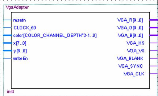
You use the VGA Adapter similar to a digital memory. This is in part because VGA Adapter uses memory to store the picture it draws on the screen. The figure below shows the input and output signals for the symbol that you would import into the schematic editor to access it. To "draw" a new pixel onto the screen, your circuit must do the following:
- Setting up the signals: x and y corresponding to the coordinates of the super pixel you wish to change. The 3-bit color[2:0] signal indicates the color you want the pixel to be. (There are 8 possible colours)
- After the values of these wires are set, your circuit should raise writeEn to high before the next positive edge of CLOCK_50 (the 50 MHz on-board clock).
The figure below shows a inputs and outputs VGA Adapter. The ports on the left are inputs, while those on the right are outputs.
Timing
The figure below gives the timing diagram for two pixels being written to the display. The first is a green pixel (colour 010) being written to positon (15, 62) on the display and the second is a red plus green pixel being written to (109, 12). As outlined, the values for the signals (color, x, y) are set up before and held after the positive edge of the clock.
Port Descriptions
The following table outlines the connections to the VGA Adapter module and their respective descriptions.
| Port Name | Description |
| resetn | This is an active low input port that causes the VGA Adapter to reset. Typically, this port is connected to the top-level reset signal in the design. |
| CLOCK_50 | The following port is used as the main clock source for the VGA Adapter. In order for the adapter to function properly, this must be connected to the 50 MHz oscillator (pin N2) on the DE2 Educational Board. |
| color[2..0] | The color bus is a 3-bit signal that defines the color of the Super Pixel to be drawn. color[2] represents red, color[1] represents green, and color[0] represents blue. It is worth mentioning that the size of this bus varies with the different color depths. This topic is further discussed in the "Changing Color Depth" section. |
| x[7..0] | These ports are used to specify the coordinates of the pixel you would like to modify. The values for x are (0-159), while the values for y are (0-119). The "VGA Adapter Basics" page provides a diagram which physically outlines which pixel these numbers represent. |
| y[6..0] | |
| writeEn | The writeEn port is used to send the specified pixel information to the VGA Adapter. If the signal is raised to high, the information from x, y and color are used and stored in the VGA Adapter module on the next positive edge of the 50 MHz clock. |
| VGA_R[9..0] | These ports are to be connected to the 10-bit DACs (Digital to Analog Converters) on the DE2 Educational Board. Once converted to analog, these signals are transmitted to the VGA monitor. |
| VGA_G[9..0] | |
| VGA_B[9..0] | |
| VGA_HS | These ports produce the horizontal and vertical sync signals for the VGA monitor. They must be connected to pins A7 and D8 respectively on the DE2 Educational Board. |
| VGA_VS | |
| VGA_BLANK | This output signal is responsible for enabling the display while the VGA Adapter is in valid pixel drawing range (i.e. not sending sync signals). This port must be connected to pin D6 on the DE2 Educational Board in the top-level design. |
| VGA_CLK | This output clock signal operates at the VGA frequency (25 MHz). This signal must be connected to pin B8 on the DE2 Educational Board in the top-level design to ensure correct operation. |