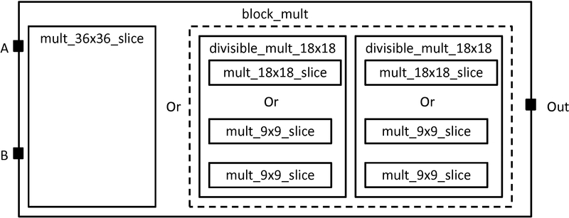
Figure 1: Model of a fracturable multiplier block
Configurable multipliers are found in today's commercial FPGAs for two primary reasons: 1) Multipliers are found in a variety of different applications including DSP, soft processors, scientific computing, etc and 2) Implementing multipliers in soft logic is very area expensive. Thus it is important for modern FPGA architects be able to describe the specific properties of the configurable multiplier that they want to investigate. The following is an example on how to use the VPR 6.0 architecture description langauge to describe a common type of configurable multiplier called a fracturable multiplier shown in Figure 1. We first give a step-by-step description on how to construct the multiplier block followed by a complete example.
Figure 1: Model of a fracturable multiplier block
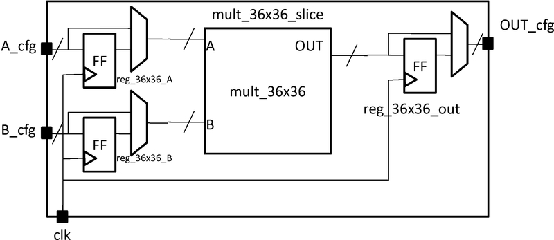
Figure 2: Multiplier slice
<pb_type name="block_mult">
  <input name="A" num_pins="36"/>
  <input name="B" num_pins="36"/>
  <output name="OUT" num_pins="72"/>
  <clock name="clk"/>
The block_mult complex block has two modes: a mode containing a 36x36 multiplier slice and a mode containing two fracturable 18x18 multipliers. The mode containing the 36x36 multiplier slice is described first. The mode and slice is declared here:
  <mode name="mult_36x36">
    <pb_type name="mult_36x36_slice" num_pb="1">
      <input name="A_cfg" num_pins="36"/>
      <input name="B_cfg" num_pins="36"/>
      <input name="OUT_cfg" num_pins="72"/>
      <clock name="clk"/>
This is followed by a description of the primitives within the slice. There are two sets of 36 flip-flops for the input ports and one set of 64 flip-flops for the output port. There is one 36x36 multiplier primitive. These primitives are described by four pb_types as follows:
      <pb_type name="reg_36x36_A" blif_model=".latch" num_pb="36" class="flipflop">
        <input name="D" num_pins="1" port_class="D"/>
        <output name="Q" num_pins="1" port_class="Q"/>
        <clock name="clk" port_class="clock"/>
      </pb_type>
      <pb_type name="reg_36x36_B" blif_model=".latch" num_pb="36" class="flipflop">
        <input name="D" num_pins="1" port_class="D"/>
        <output name="Q" num_pins="1" port_class="Q"/>
        <clock name="clk" port_class="clock"/>
      </pb_type>
      <pb_type name="reg_36x36_out" blif_model=".latch" num_pb="72" class="flipflop">
        <input name="D" num_pins="1" port_class="D"/>
        <output name="Q" num_pins="1" port_class="Q"/>
        <clock name="clk" port_class="clock"/>
      </pb_type>

      <pb_type name="mult_36x36" blif_model=".subckt mult" num_pb="1">
        <input name="A" num_pins="36"/>
        <input name="B" num_pins="36"/>
        <output name="OUT" num_pins="72"/>
      </pb_type>
The slice description finishes with a specification of the interconnection. Using the same technique as in the memory example, bus-based multiplexers are used to register the ports. Clocks are connected using the complete tag because there is a one-to-many relationship. Direct tags are used to make simple, one-to-one connections.
      <interconnect>
        <direct input="mult_36x36_slice.A_cfg" output="reg_36x36_A[35:0].D"/>
        <direct input="mult_36x36_slice.B_cfg" output="reg_36x36_B[35:0].D"/>
        <mux input="mult_36x36_slice.A_cfg reg_36x36_A[35:0].Q" output="mult_36x36.A"/>
        <mux input="mult_36x36_slice.B_cfg reg_36x36_B[35:0].Q" output="mult_36x36.B"/>

        <direct input="mult_36x36.OUT" output="reg_36x36_out[71:0].D"/>
        <mux input="mult_36x36.OUT reg_36x36_out[71:0].Q" output="mult_36x36_slice.OUT_cfg"/>

        <complete input="mult_36x36_slice.clk" output="reg_36x36_A[35:0].clk"/>
        <complete input="mult_36x36_slice.clk" output="reg_36x36_B[35:0].clk"/>
        <complete input="mult_36x36_slice.clk" output="reg_36x36_out[71:0].clk"/>
      </interconnect>
    </pb_type>
The mode finishes with a specification of the interconnect between the slice and its parent.
    <interconnect>
      <direct input="block_mult.A" output="mult_36x36_slice.A_cfg"/>
      <direct input="block_mult.B" output="mult_36x36_slice.A_cfg"/>
      <direct input="mult_36x36_slice.OUT_cfg" output="block_mult.OUT"/>
      <direct input="block_mult.clk" output="mult_36x36_slice.clk"/>
    </interconnect>
  </mode>
After the mode containing the 36x36 multiplier slice is described, the mode containing two fracturable 18x18 multipliers is described:
  <mode name="two_divisible_mult_18x18">
    <pb_type name="divisible_mult_18x18" num_pb="2">
      <input name="A" num_pins="18"/>
      <input name="B" num_pins="18"/>
      <input name="OUT" num_pins="36"/>
      <clock name="clk"/>
This mode has two additional modes which are the actual 18x18 multiply block or two 9x9 mulitplier blocks. Both follow a similar description as the mult\_36x36\_slice with just the number of pins halved so the details are not repeated.
      <mode  name="two_divisible_mult_18x18">
        <pb_type name="mult_18x18_slice" num_pb="1">
          <!-- follows previous pattern for slice definition -->
        </pb_type>
        <interconnect>
          <!-- follows previous pattern for slice definition -->
        </interconnect>
      </mode>

      <mode name="two_mult_9x9">
        <pb_type name="mult_9x9_slice" num_pb="2">
          <!-- follows previous pattern for slice definition -->
        </pb_type>
        <interconnect>
          <!-- follows previous pattern for slice definition -->
        </interconnect>
      </mode>

    </pb_type>
The interconnect for the divisible 18x18 mode is shown in \autoref{fig:pl_mult_cluster}. The unique characteristic of this interconnect is that the input and output ports of the parent is split in half, one half for each child. A convenient way to specify this is to use the syntax divisible_mult_18x18[1:0] which will append the pins of the ports of the children together. The interconnect for the fracturable 18x18 mode is described here:
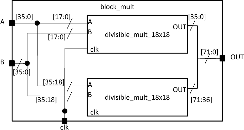
Figure 3: Multiplier slice
    <interconnect>
      <direct input="block_mult.A" output="divisible_mult_18x18[1:0].A"/>
      <direct input="block_mult.B" output="divisible_mult_18x18[1:0].B"/>
      <direct input="divisible_mult_18x18[1:0].OUT" output="block_mult.OUT"/>
      <complete input="block_mult.clk" output="divisible_mult_18x18[1:0].clk"/>
    </interconnect>
  </mode>
</pb_type>
<!-- Example of a fracturable mutliplier whose inputs and outputs may be optionally registered
The multiplier hard logic block can implement one 36x36, two 18x18, or four 9x9 multiplies
-->
<pb_type name="block_mult">
  <input name="A" num_pins="36"/>
  <input name="B" num_pins="36"/>
  <output name="OUT" num_pins="72"/>
  <clock name="clk"/>

  <mode name="mult_36x36">
    <pb_type name="mult_36x36_slice" num_pb="1">
      <input name="A_cfg" num_pins="36" equivalence="false"/>
      <input name="B_cfg" num_pins="36" equivalence="false"/>
      <input name="OUT_cfg" num_pins="72" equivalence="false"/>
      <clock name="clk"/>

      <pb_type name="reg_36x36_A" blif_model=".latch" num_pb="36" class="flipflop">
        <input name="D" num_pins="1" port_class="D"/>
        <output name="Q" num_pins="1" port_class="Q"/>
        <clock name="clk" port_class="clock"/>
      </pb_type>
      <pb_type name="reg_36x36_B" blif_model=".latch" num_pb="36" class="flipflop">
        <input name="D" num_pins="1" port_class="D"/>
        <output name="Q" num_pins="1" port_class="Q"/>
        <clock name="clk" port_class="clock"/>
      </pb_type>
      <pb_type name="reg_36x36_out" blif_model=".latch" num_pb="72" class="flipflop">
        <input name="D" num_pins="1" port_class="D"/>
        <output name="Q" num_pins="1" port_class="Q"/>
        <clock name="clk" port_class="clock"/>
      </pb_type>

      <pb_type name="mult_36x36" blif_model=".subckt mult" num_pb="1">
        <input name="A" num_pins="36"/>
        <input name="B" num_pins="36"/>
        <output name="OUT" num_pins="72"/>
      </pb_type>

      <interconnect>
        <direct input="mult_36x36_slice.A_cfg" output="reg_36x36_A[35:0].D"/>
        <direct input="mult_36x36_slice.B_cfg" output="reg_36x36_B[35:0].D"/>
        <mux input="mult_36x36_slice.A_cfg reg_36x36_A[35:0].Q" output="mult_36x36.A"/>
        <mux input="mult_36x36_slice.B_cfg reg_36x36_B[35:0].Q" output="mult_36x36.B"/>

        <direct input="mult_36x36.OUT" output="reg_36x36_out[71:0].D"/>
        <mux input="mult_36x36.OUT reg_36x36_out[71:0].Q" output="mult_36x36_slice.OUT_cfg"/>

        <complete input="mult_36x36_slice.clk" output="reg_36x36_A[35:0].clk"/>
        <complete input="mult_36x36_slice.clk" output="reg_36x36_B[35:0].clk"/>
        <complete input="mult_36x36_slice.clk" output="reg_36x36_out[71:0].clk"/>
      </interconnect>
    </pb_type>
    <interconnect>
      <direct input="block_mult.A" output="mult_36x36_slice.A_cfg"/>
      <direct input="block_mult.B" output="mult_36x36_slice.A_cfg"/>
      <direct input="mult_36x36_slice.OUT_cfg" output="block_mult.OUT"/>
      <direct input="block_mult.clk" output="mult_36x36_slice.clk"/>
    </interconnect>
  </mode>

  <mode  name="two_divisible_mult_18x18">
    <pb_type name="divisible_mult_18x18" num_pb="2">
      <input name="A" num_pins="18"/>
      <input name="B" num_pins="18"/>
      <input name="OUT" num_pins="36"/>
      <clock name="clk"/>

      <mode name="mult_18x18">
        <pb_type name="mult_18x18_slice" num_pb="1">
          <input name="A_cfg" num_pins="18"/>
          <input name="B_cfg" num_pins="18"/>
          <input name="OUT_cfg" num_pins="36"/>
          <clock name="clk"/>

          <pb_type name="reg_18x18_A" blif_model=".latch" num_pb="18" class="flipflop">
            <input name="D" num_pins="1" port_class="D"/>
            <output name="Q" num_pins="1" port_class="Q"/>
            <clock name="clk" port_class="clock"/>
          </pb_type>
          <pb_type name="reg_18x18_B" blif_model=".latch" num_pb="18" class="flipflop">
            <input name="D" num_pins="1" port_class="D"/>
            <output name="Q" num_pins="1" port_class="Q"/>
            <clock name="clk" port_class="clock"/>
          </pb_type>
          <pb_type name="reg_18x18_out" blif_model=".latch" num_pb="36" class="flipflop">
            <input name="D" num_pins="1" port_class="D"/>
            <output name="Q" num_pins="1" port_class="Q"/>
            <clock name="clk" port_class="clock"/>
          </pb_type>

          <pb_type name="mult_18x18" blif_model=".subckt mult" num_pb="1">
            <input name="A" num_pins="18"/>
            <input name="B" num_pins="18"/>
            <output name="OUT" num_pins="36"/>
          </pb_type>

          <interconnect>
            <direct input="mult_18x18_slice.A_cfg" output="reg_18x18_A[17:0].D"/>
            <direct input="mult_18x18_slice.B_cfg" output="reg_18x18_B[17:0].D"/>
            <mux input="mult_18x18_slice.A_cfg reg_18x18_A[17:0].Q" output="mult_18x18.A"/>
            <mux input="mult_18x18_slice.B_cfg reg_18x18_B[17:0].Q" output="mult_18x18.B"/>

            <direct input="mult_18x18.OUT" output="reg_18x18_out[35:0].D"/>
            <mux input="mult_18x18.OUT reg_18x18_out[35:0].Q" output="mult_18x18_slice.OUT_cfg"/>

            <complete input="mult_18x18_slice.clk" output="reg_18x18_A[17:0].clk"/>
            <complete input="mult_18x18_slice.clk" output="reg_18x18_B[17:0].clk"/>
            <complete input="mult_18x18_slice.clk" output="reg_18x18_out[35:0].clk"/>
          </interconnect>
        </pb_type>
        <interconnect>
          <direct input="divisible_mult_18x18.A" output="mult_18x18_slice.A_cfg"/>
          <direct input="divisible_mult_18x18.B" output="mult_18x18_slice.A_cfg"/>
          <direct input="mult_18x18_slice.OUT_cfg" output="divisible_mult_18x18.OUT"/>
          <complete input="divisible_mult_18x18.clk" output="mult_18x18_slice.clk"/>
        </interconnect>
      </mode>

      <mode name="two_mult_9x9">
        <pb_type name="mult_9x9_slice" num_pb="2">
          <input name="A_cfg" num_pins="9"/>
          <input name="B_cfg" num_pins="9"/>
          <input name="OUT_cfg" num_pins="18"/>
          <clock name="clk"/>

          <pb_type name="reg_9x9_A" blif_model=".latch" num_pb="9" class="flipflop">
            <input name="D" num_pins="1" port_class="D"/>
            <output name="Q" num_pins="1" port_class="Q"/>
            <clock name="clk" port_class="clock"/>
          </pb_type>
          <pb_type name="reg_9x9_B" blif_model=".latch" num_pb="9" class="flipflop">
            <input name="D" num_pins="1" port_class="D"/>
            <output name="Q" num_pins="1" port_class="Q"/>
            <clock name="clk" port_class="clock"/>
          </pb_type>
          <pb_type name="reg_9x9_out" blif_model=".latch" num_pb="18" class="flipflop">
            <input name="D" num_pins="1" port_class="D"/>
            <output name="Q" num_pins="1" port_class="Q"/>
            <clock name="clk" port_class="clock"/>
          </pb_type>

          <pb_type name="mult_9x9" blif_model=".subckt mult" num_pb="1">
            <input name="A" num_pins="9"/>
            <input name="B" num_pins="9"/>
            <output name="OUT" num_pins="18"/>
          </pb_type>

          <interconnect>
            <direct input="mult_9x9_slice.A_cfg" output="reg_9x9_A[8:0].D"/>
            <direct input="mult_9x9_slice.B_cfg" output="reg_9x9_B[8:0].D"/>
            <mux input="mult_9x9_slice.A_cfg reg_9x9_A[8:0].Q" output="mult_9x9.A"/>
            <mux input="mult_9x9_slice.B_cfg reg_9x9_B[8:0].Q" output="mult_9x9.B"/>

            <direct input="mult_9x9.OUT" output="reg_9x9_out[17:0].D"/>
            <mux input="mult_9x9.OUT reg_9x9_out[17:0].Q" output="mult_9x9_slice.OUT_cfg"/>

            <complete input="mult_9x9_slice.clk" output="reg_9x9_A[8:0].clk"/>
            <complete input="mult_9x9_slice.clk" output="reg_9x9_B[8:0].clk"/>
            <complete input="mult_9x9_slice.clk" output="reg_9x9_out[17:0].clk"/>
          </interconnect>
        </pb_type>
        <interconnect>
          <direct input="divisible_mult_18x18.A" output="mult_9x9_slice[1:0].A_cfg"/>
          <direct input="divisible_mult_18x18.B" output="mult_9x9_slice[1:0].A_cfg"/>
          <direct input="mult_9x9_slice[1:0].OUT_cfg" output="divisible_mult_18x18.OUT"/>
          <complete input="divisible_mult_18x18.clk" output="mult_9x9_slice[1:0].clk"/>
        </interconnect>
      </mode>
    </pb_type>
    <interconnect>
      <direct input="block_mult.A" output="divisible_mult_18x18[1:0].A"/>
      <direct input="block_mult.B" output="divisible_mult_18x18[1:0].B"/>
      <direct input="divisible_mult_18x18[1:0].OUT" output="block_mult.OUT"/>
      <complete input="block_mult.clk" output="divisible_mult_18x18[1:0].clk"/>
    </interconnect>
  </mode>

  <fc_in type="frac">0.15</fc_in>
  <fc_out type="frac">0.125</fc_out>

  <pinlocations pattern="custom">
    <loc side="left">a[35:0]</loc>
    <loc side="left" offset="1">b[35:0]</loc>
    <loc side="right">out[19:0]</loc>
    <loc side="right" offset="1">out[39:20]</loc>
    <loc side="right" offset="2">out[63:40]</loc>
  </pinlocations>

  <gridlocations>
    <loc type="col" start="4" repeat="5" priority="2"/>
  </gridlocations>
</pb_type>