Lecture 19.1
Andreas Moshovos
Spring 2007
Modifying the Single-Cycle
CPU Implementation
What if we decided to change the definition of the ADD instruction as follows. Instead of ADD OpA OpB we want to have ADD OpA (OpB). The new ADD replaces the previous one. So the encoding remains:
ADD
|
7 |
6 |
5 |
4 |
3 |
2 |
1 |
0 |
|
OpA |
OpA |
OpB |
OpB |
0 |
1 |
0 |
0 |
However,
the instruction now performs the following actions:
ADD
OpA (OpB)
TMP = MEM[OpB]
TMP = OpA + TMP
OpA = TMP
IF (TMP == 0) ZERO = 1; ELSE ZERO =
0;
IF (TMP < 0) NEGATIVE = 1; ELSE
NEGATIVE = 0;
PC = PC + 1
What needs to change in the datapath and control?
Datapath Modifications
Recall that the datapath should be able to perform all the actions necessary by any instruction. So what are the actions necessary for the new ADD instruction?
- We must be able to read an instruction from memory using the PC as the address
- We must be able to use field “OpB” from the instruction to specify a register to read from.
- We must be able to use the value read from the register file in step 2 and use it from memory to read a byte.
- We must be able to use field “OpA” from the instruction to specify a register to read from.
- We must be able to add the values read in steps 3 and 4.
- We must be able to use field “OpA” from the instruction to specify a register to write into the value generated in step 5.
- We must be able to update Z and N according to the value produced in step 5.
- Must be able to read PC, add 1 and write the result PC+1 back into the PC.
Here’s the datapath we designed thus far:
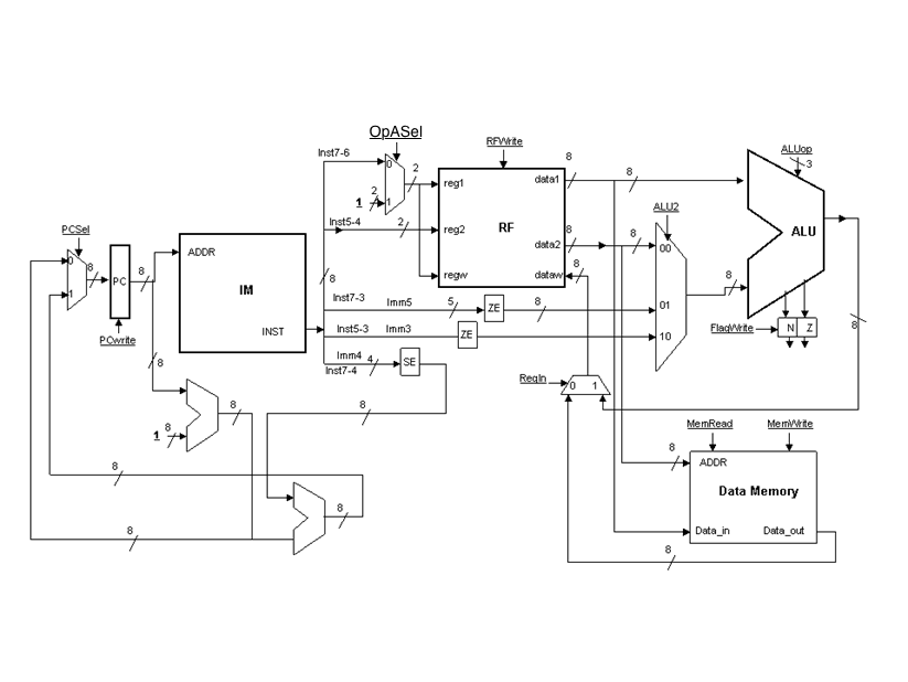
Let’s see which of the 8 actions this datapath can’t do. It can’t do 5. Everything else is possible. So, at the end what is needed is a way of passing the value read from memory as the second input to the ALU.
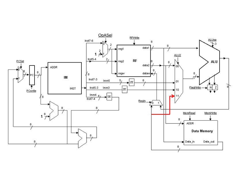
Here’s the modified datapath:
Control
Modifications:
Since we only changed the ADD instruction we need to change the row for the ADD instruction only. Note that the meaning of some control signals is different here compared to the previous lecture. RFin 1 means pass the value of the ALU to the register file, and RFin 0 means pass the value of the Data Memory.
|
INSTRUCTION |
Inputs |
Outputs |
||||||||||
|
|
INST0-3 |
N |
Z |
PCSel |
PCWrite |
RegWrite |
MemRead |
OpASel |
MemWrite |
ALU2 |
RFin |
ALUop |
|
ADD |
0100 |
X |
X |
0 |
1 |
1 |
1 |
0 |
0 |
11 |
1 |
000 |