ECE243
Andreas Moshovos
Spring 2008
The Timer Device
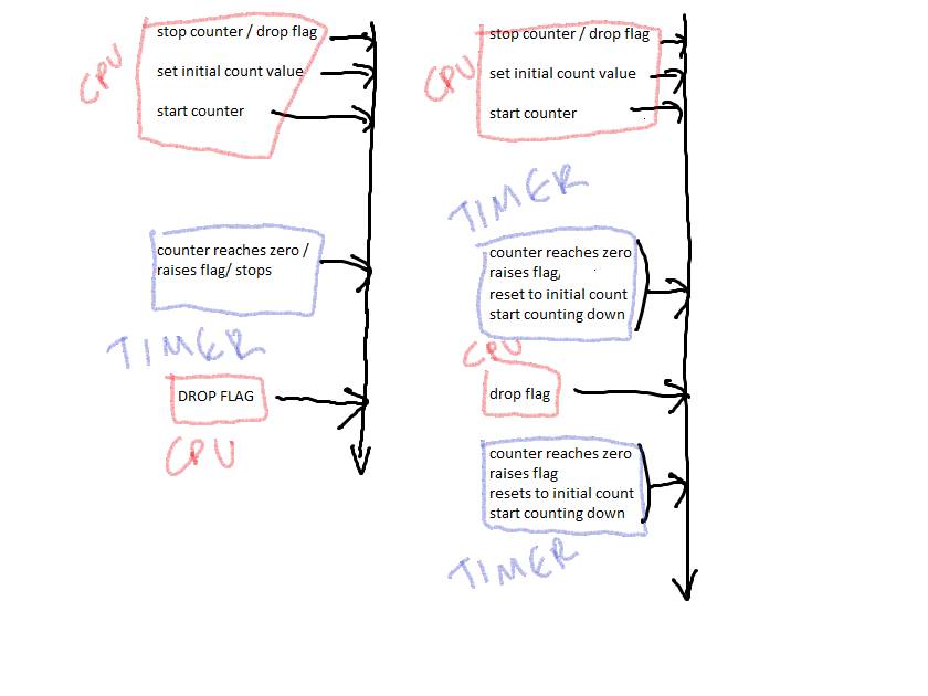
In this lecture we will discuss the timer device. The timer allows programs to measure absolute time and can be used in applications where real-time behavior is important. One such application would be a stop-watch. The timer is a 32-bit counter that counts down using a fixed clock. The counter also contains an indicator, think of it as a flag. Initially, you drop the flag, set the counter to some value, and start it. When it reaches zero, the timer raises the flag. When you see the flag raised, you can reset the counter to its initial value, drop the flag, and have it count again down to zero. A raised flag indicates that the desired time period has elapsed. The aforementioned process allows us to measure intervals of time with good accuracy. Alternatively, you can have the counter auto-reset after reaching zero. As soon as the counter reaches zero, it raises the flag, and automatically reloads the initial value you set earlier. You have to go and drop the flag before it reaches zero again. This way the timer can generate periodic signals without relying on us (the processor) to drop the flag and reset the counter at every interval.
So, here are the two ways the counter is meant to be used:
Count-Once
Mode:
Continuous-Count Mode:
The timer device is mapped onto memory starting at address 0x10002000. The timer contains six 32-bit registers, but only the lower 16 bits of each register are in use:
|
Offset |
Name |
31 |
|
|
|
|
|
|
|
|
|
|
|
|
|
|
|
15 |
|
|
|
|
|
|
8 |
7 |
6 |
5 |
4 |
3 |
2 |
1 |
0 |
|
0 |
status |
Undefined / Use 0 when writing |
|
RUN |
TO |
||||||||||||||||||||||||||||
|
4 |
control |
Undefined / Use 0 when writing |
|
STOP |
START |
CONT |
ITO |
||||||||||||||||||||||||||
|
8 |
periodl |
Undefined / Use 0 when writing |
Lower 16 bits of counting period |
||||||||||||||||||||||||||||||
|
12 |
periodh |
Undefined / Use 0 when writing |
Upper 16 bits of counting period |
||||||||||||||||||||||||||||||
|
16 |
snapl |
Undefined / Use 0 when writing |
Lower 16 bits of current count |
||||||||||||||||||||||||||||||
|
20 |
snaph |
Undefined / Use 0 when writing |
Upper 16 bits of current count |
||||||||||||||||||||||||||||||
The timer is a 32-bit counter that counts downwards to zero using a 100Mhz clock. In a typical application, our program would initialize the counter to a specific count and then wait until the counter reaches zero. The control register can be used to start or stop the counter. The timer can be configured to restart over automatically or to stop and wait. In this former case, when the counter reaches zero, it re-loads the initial count we set before starting it for the first time and starts counting down to zero again without any program intervention. This is useful for measuring periodic intervals with great accuracy and for generating periodic signals such as pulses for audio or for driving motors. The status register can be used to check whether the counter is currently counting (RUN bit) and whether the counter has reached zero (TO = TimeOut bit). Our program can also inspect the SNAP registers in the timer device to determine how much time has elapsed since the countdown was initiated. The timer can also be configured to notify our programs through interrupts that zero has been reached. More on this later.
Let’s see how we can use the timer to generate a stop watch that counts down in seconds.
What we need is to set the timer so that it generates a period of one second. Since the clock used by the counter is 100Mhz or 100 x 10^6 = 10^7 Hz. We need to count 10^7 ticks for every second elapsed and we need to keep doing this until the number of seconds we are interested in have elapsed. So, we need to ask the counter to start counting down from 10^7.
Before we start initializing the timer we got to make sure it’s idle. This is done by sending the STOP command, which is done by setting the STOP bit (bit 3) of the control register to 1.
Assuming that we have made the following constant declarations:
.equ TIMER0_BASE, 0x10002000
.equ TIMER0_STATUS, 0
.equ TIMER0_CONTROL, 4
.equ TIMER0_PERIODL, 8
.equ TIMER0_PERIODH, 12
.equ TIMER0_SNAPL, 16
.equ TIMER0_SNAPH, 20
Here’s how to stop the timer:
movia r8, TIMER0_BASE
addi r9, r0, 0x8
stwio r9, TIMER0_CONTROL(r8)
Next we can initialize the period registers so that when the counter starts it will count down from 10^7.
This is done by writing to registers periodl and periodh. Each is 16-bits and together they form a 32-bit number. The code for initializing the period registers is:
.equ TICKSPERSEC, 100000000
# Set the period registers to 10^7
addi r9, r0, lo%(TICKSPERSEC)
stwio r9, TIMER0_PERIODL(r8)
addi r9, r0, %hi(TICKSPERSEC)
stwio r9, TIMER0_PERIODH(r8)
Where we used the assembly macros %lo() and %hi() to decompose the 32-bit period value into a 16-bit lower component and a 16-bit upper component.
For illustration purposes we will have the counter continue counting after a second has passed. This is done by setting bit CONT (bit 1) of the control register. At the same time we can tell the counter to start counting. This is done by setting bit START (bit 2) to 1.
# tell the counter to start over
automatically and start counting
addi r9,
r0, 0x6 # 0x6 = 0110 so
we write 1 to START and to CONT
stwio r9, TIMER0_CONTROL(r8)
To check whether zero has been reached we can poll the status register:
Bit 1, or RUN, tells us whether the counter is running. This should be 1 after the last store.
Bit 0, or bit TO for TimeOut, is 1 if the counter has reached zero. The TO bit remains stuck at 1 unless we explicitly clear it.
Here’s the complete code for a “stopwatch”. The function takes a single argument which is a number of seconds to wait.
It returns when this many seconds have elapsed. The argument is a 32 bit unsigned number.
.equ TIMER0_BASE, 0x10002000
.equ TIMER0_STATUS, 0
.equ TIMER0_CONTROL, 4
.equ TIMER0_PERIODL, 8
.equ TIMER0_PERIODH, 12
.equ TIMER0_SNAPL, 16
.equ TIMER0_SNAPH, 20
.equ TICKSPERSEC, 1000000000
.text
waitasec:
movia r8, TIMER0_BASE
addi r9, r0, 0x8 # stop the counter
stwio r9, TIMER0_CONTROL(r8)
# Set the period registers to 10^7
addi r9, r0, %lo (TICKSPERSEC)
stwio r9, TIMER0_PERIODL(r8)
addi r9, r0, %hi(TICKSPERSEC)
stwio r9, TIMER0_PERIODH(r8)
# tell the counter to start over
automatically and start counting
addi r9,
r0, 0x6 # 0x6 = 0110 so
we write 1 to START and to CONT
stwio r9, TIMER0_CONTROL(r8)
onesec:
ldwio r9, TIMER0_STATUS(r8) # check if the TO bit of the status register is 1
andi r9, r9, 0x1
beq r9, r0, onesec
movi r9, 0x0 # clear the TO bit
stwio r9, TIMER0_STATUS(r8)
# decrement the number of remaining seconds and repeat until this becomes zero
subi r4, r4, 1
bne r4, r0, onesec
# stop the counter before exiting
movi r9, 8
stwio r9, TIMER0_CONTROL(r8)
ret
And here’s a function that calls waitasec asking it to wait for 20 seconds:
.text
.global main
main:
addi r4, r0, 20
call waitasec
ret
Reading the
counter’s current value
We cannot and should not access the period registers to check what is the current value. Instead this can be done via the Snap registers. First we take a snapshot of the period registers and then we read it out. To take a snapshot of the period registers we have to write 0 to SnapL. At that moment, the timer copies the values of periodl and periodh to snapl and snaph respetively. We can then read the two snap registers. Here’s the code for that:
movia r8, TIMER0_BASE
stwio r0, TIMER0_SNAPL(r7) # Take a snapshot of the period registers
ldwio r9, TIMER0_SNAPL(r7) # Read snapshot bits 0..15
ldwio r10, TIMER0_SNAPH(r7) # Read snapshot bits 16...31
slli r10, r10, 16 # Shift the upper bits to positions 16 through 31 in register r10
or r9, r9, r10 # Combine bits 0..15 and 16...31 into one register
Other bits
The timer can also generate interrupts. Bit ITO of the control register instructs the timer to generate an interrupt when zero is reached. We’ll defer further discussion of interrupts and the timer for later. Timer0 is connected to IRQ3 and TIMER1 to IRQ4.