ECE243
Loads and Stores in NIOS II
Andreas Moshovos
Spring 2008
In this note we will be taking a closer look at the way loads and stores work in NIOS II.
Let’s assume the following initial state for a few registers:
|
Register |
|
contents |
|||
|
r8 |
0x |
01 |
00 |
00 |
60 |
|
r9 |
0x |
00 |
00 |
00 |
00 |
|
r10 |
0x |
00 |
00 |
00 |
00 |
|
r11 |
0x |
00 |
00 |
00 |
00 |
And for some memory locations:
|
address |
|
|
0x10000060 |
0x01 |
|
0x10000061 |
0xFF |
|
0x10000062 |
0x03 |
|
0x10000063 |
0x04 |
|
0x10000064 |
0x11 |
|
0x10000065 |
0x22 |
|
0x10000066 |
0x33 |
|
0x10000067 |
0x44 |
Let’s see what happens when the following instruction is executed:
ldwio r9, 0(r8)
This is what the following diagram shows:
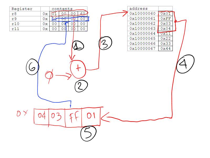
Here are the steps:
- First we read the value of register r8. The value is 0x1000060
- Then we add 0 to that value. The result is 0x1000060. Register r8 is not changed.
- We send the result of step 2 to memory asking it to read a word starting from the corresponding address.
- Memory reads four bytes starting from memory address 0x1000060.
- The four bytes are assembled into a word in little-endian order. The result is the word 0x0403ff01.
- The word is written into register r9.
Now let’s see what stwio r9, 4(r8) does assuming it follows the previous load:
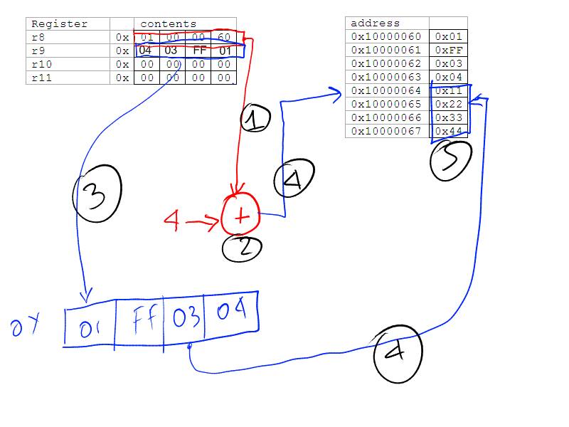
The steps here are:
1. Read the value of r8. This is 0x1000060
2. Add 4 to the value read in step 8. r8 is not changed. The result is 0x1000064.
3. Read the value of register r9 and assemble the bytes in little endian-order to get 0x01ff0304
4. Send the value calculated in step 2 as an address and the value of step 3 as data to memory and ask it to perform a store.
5. Memory writes the four bytes given starting from address 0x1000064. The diagram does not show the final result in memory. At the end memory will look as follows:
|
address |
|
|
0x10000060 |
0x01 |
|
0x10000061 |
0xFF |
|
0x10000062 |
0x03 |
|
0x10000063 |
0x04 |
|
0x10000064 |
0x01 |
|
0x10000065 |
0xFF |
|
0x10000066 |
0x03 |
|
0x10000067 |
0x04 |
Now let’s see what happens when this executes after the previous two instructions:
ldhio r9, 4(r8)
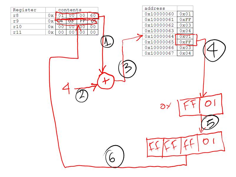
Here are the steps:
1. Read the value of register r8. This is 0x1000060
2. Add 4 to that value. The result is 0x1000064.
3. Ask memory to read two bytes starting from address 0x1000064. It’s two bytes because this is ldhio and not ldwio.
4. Memory reads the two bytes and assembles them into little-endian order to get 0xFF01.
5. The value of step 4 gets sign-extended to 32 bits to become 0xFFFFFF01. The sign of 0xFF01 is 1 (the number is 1111 1111 0000 0001 in binary and sign is the leftmost bit). Sign-extension is used because this is ldhio and not ldhuio.
6. The value is written into r9. The final state of r9 is not shown in the diagram. The final register state is:
|
Register |
|
contents |
|||
|
r8 |
0x |
01 |
00 |
00 |
60 |
|
r9 |
0x |
FF |
FF |
FF |
01 |
|
r10 |
0x |
00 |
00 |
00 |
00 |
|
r11 |
0x |
00 |
00 |
00 |
00 |
If the instruction was “ldhuio r9, 4(r8)” the final result would have been r9=0x0000FF01. The only thing that would have been done differently is that in step 5 we would have used zero-extension as opposed to sign-extension.
Let’s now look at:
ldhio r9, 6(r8)
Here’s what happens:
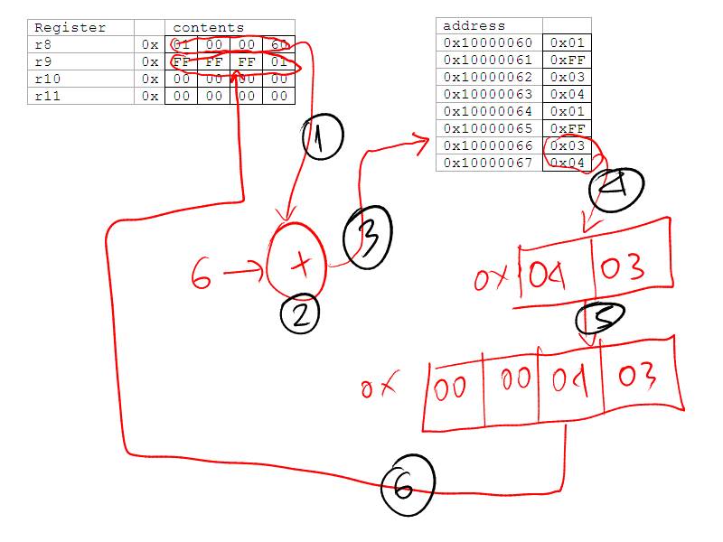
1. Read the value of register r8. This is 0x1000060
2. Add 6 to that value. The result is 0x1000066.
3. Ask memory to read two bytes starting from address 0x1000066. It’s two bytes because this is ldhio and not ldwio.
4. Memory reads the two bytes and assembles them into little-endian order to get 0x0403.
5. The value of step 4 gets sign-extended to 32 bits to become 0x00000403. The sign of 0x0403 is 0 (the number is 0000 0000 0100 0011 in binary and sign is the leftmost bit). Sign-extension is used because this is ldhio and not ldhuio.
6. The value is written into r9. The final state of r9 is not shown in the diagram. The final register state is:
|
Register |
|
contents |
|||
|
r8 |
0x |
01 |
00 |
00 |
60 |
|
r9 |
0x |
00 |
00 |
04 |
03 |
|
r10 |
0x |
00 |
00 |
00 |
00 |
|
r11 |
0x |
00 |
00 |
00 |
00 |
Let’s now do:
addi r8, r8, 8
So that r8 becomes 0x01000068:
|
Register |
|
contents |
|||
|
r8 |
0x |
01 |
00 |
00 |
68 |
|
r9 |
0x |
00 |
00 |
04 |
03 |
|
r10 |
0x |
00 |
00 |
00 |
00 |
|
r11 |
0x |
00 |
00 |
00 |
00 |
What will this do?
ldbio r9, -3(r8)
Here are the steps:
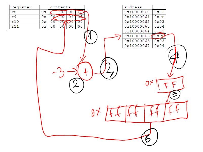
1. Read the value of register r8. This is 0x1000068
2. Add -3to that value. The result is 0x1000065.
3. Ask memory to read one byte starting from address 0x1000065. It’s one bytes because this is ldb.
4. Memory reads the byte which is 0xFF.
5. The value of step 4 gets sign-extended to 32 bits to become 0xFFFFFFFF. The sign of 0xFF is 1 (the number is 1111 1111 in binary and sign is the leftmost bit). Sign-extension is used because this is ldbio and not ldbuio.
6. The value is written into r9. The final state of r9 is not shown in the diagram. The final register state is:
|
Register |
|
contents |
|||
|
r8 |
0x |
01 |
00 |
00 |
68 |
|
r9 |
0x |
FF |
FF |
FF |
FF |
|
r10 |
0x |
00 |
00 |
00 |
00 |
|
r11 |
0x |
00 |
00 |
00 |
00 |