ECE241F Lab 5
2.0 Background
Read Section 5.1 and 5.2 of the text to learn about binary number representation, and how to build a ripple-carry adder.
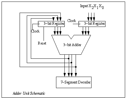
Using the 3-bit register (with reset) that you built in lab 4, and the seven-segment decoder you built in Lab 3 you will build an adder unit, as shown in Figure 1, whose inputs are: a single three-bit binary number (X2X1X0) the clock, and the Reset signal. The four-bit output of the adder is connected to the 7-segment display so that it can be viewed. In the preparation below, you are required to figure out how to use this circuit to add two three-bit numbers. This is actually a simple version of the arithmetic and logic unit found inside all computers.