ECE241F Lab 7
2.0 Background
- In Lab #5 you created a 3-bit D-type register (which was simply three D Flip-flops with the clock signals connected together), that also had a reset signal which set all of the flip-flops to zero when activated. A register with an Enable signal works in the following way: if the enable = 1, then the register works as usual. If enable = 0, then the outputs (Qi) do not change in response to the clock.
- 2. The Altera maxplus2 software provides you with a number of pre-designed units, which they call Library of Parameterized Modules (LPM). These consist of adders, adder/subtracters, multipliers, shift registers, decoders and more - basically everything we get you to design in this course, already done for you. The meaning of the word "parameterized" here is that you can specify many different things about the module. For example, you can call up an adder and specify that it should be a 10 bit adder, or a 20-bit adder. You can specify that a multi-bit D register has an enable signal (or not).
To look at the different modules that are available, bring up the graphic editor in maxplus2 and double-click to bring up the Enter Symbol dialog box. Select the library that ends with "mega_lpm." The list of symbols that appear are the different modules. Scroll down the list and select the module lpm_add_sub. This is a module that will act either as an adder or a subtracter, depending on the value of a control.
When you select the lpm_add_sub, a symbol appears on the graphic editor and at the same time a dialog box appears. This dialog box allows you to provide specifications of what type of adder/subtracter that you want. For example to say that you want a 3-bit adder/subtracter, select the parameter from the list at the bottom labelled "LPM_WIDTH" by double clicking on it. In the field next to "parameter value" type the value 3.
To specify that you want this to be an adder/subtracter unit (as opposed to simply an adder), in the list at the top of the dialog box, select the name "add_sub" and click on the "used" button under Port Status. This creates a signal, attached to the adder, called add_sub, which when set to 1, causes the device to add its two inputs, and when set to 0, makes it subtract them. (Later in class, we will show a circuit that does this).
To learn more about the various parameters of this module, click on the "HELP" button in the dialog box, use the main help menu, under MEGAFUNCTIONS/LPM.
Click OK in the dialog box to create the adder/subtracter. You can modify your choices by double-clicking on the list of parameters that appear in the graphic editor.
- 3. To transmit data between two devices, it is often necessary to provide what are called "handshaking" signals that ensure that the data is received correctly, particularly when two devices are running at very different speeds. Consider the situation illustrated in Figure 1, in which
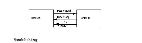 n bits of data are to be transmitted from Device #2 to Device #1. When Device #1 requires new data, it raises the Data_Request line high. Once #2 sees this and has placed the correct data on the n Data lines, it raises the Data_Ready line high. When #1 has taken the data (typically stored in a D-register) it lowers the Data_Request line after which #2 lowers the Data_Ready line. Device #1 can only raise a new request after the Data_Ready line is lowered. This procedure is called a "full handshake" and ensures that the data is transferred correctly, even when the two devices are running at vastly different speeds.
We will make use of this concept in this lab, because Device #1 will be a state machine running at 25 MHz, and device #2, will be you, (i.e. you will be providing both the data through switches, and the Data_Ready signal) and you run considerably slower than 25MHz.