ECE241F Lab 7
3.0 Preparation
Note: all preparation schematics, VHDL code and simulation output MUST BE PRINTED on paper for marking, before the lab begins.
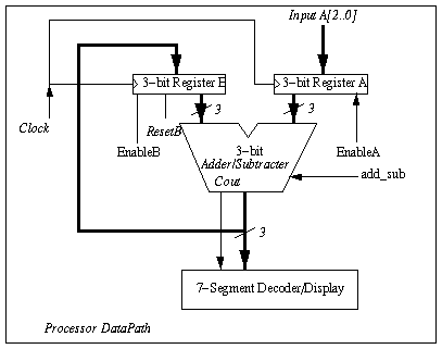
- Create a 3-bit D-type register symbol that has a Reset signal and an Enable signal as described above (either by creating your own symbol from basic DFFs or by using module lpm_DFF). Simulate your register to be sure that you understand how the Enable works.
- 2. Create a 3-bit adder/subtracter LPM unit in the graphic editor, (with an add_sub control signal) as described in part 2 of the background. Simulate the unit to make sure that you understand how it works. It is easier to simulate if you keep the 3-bit inputs grouped together as a bus, and in the waveform editor, specify these values as a group.
- 3. Build the circuit of Figure 2 in the graphic editor. Simulate the use of this circuit to add two numbers, applied one at a time through the input A, similar to Lab #5.
- 4. Using the circuit of Figure 2, simulate the subtraction of two numbers. (Setting add_sub = 0 makes this unit a subtracter).
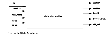
- 5. You are to design a finite state machine that controls the circuit of Figure 2, and interacts with you as the user. The clock signal (for both the finite state machine and the Registers A and B) will be connected to the 25MHz (period 40ns) clock signal that is generated on the Altera board, and appears at pin #83 of the MAX 7128 (the global clock input).
The outputs of the finite state machine (illustrated in Figure 3) are:
- EnableA - the enable signal for register A. When this is turned on, register A will, on the next positive edge of the clock, copy the input data A[2..0], coming from user switches into register A.
- ii. EnableB - the enable signal for register B. When this is turned on, register B will, on the next positive edge of the clock, copy the output of the adder/subtracter into register B.
- iii. ResetB - an active low signal which should set the contents of register B to zero.
- iv. Request_Data - is an output (to be hooked up to a light on the digital switch board) which will signal to you that the machine wants you to input data.
- v. add_sub - is connected to the add_sub signal of the adder/subtracter, to tell it which function to perform. (=1 means add, =0 means subtract)
The inputs of the finite state machine are:
- GO - active low. When activated, this causes the machine to begin operation, as described below.
- ii. Function - this is an input from the user which indicates the "instruction" that is desired - = 1 means that the two numbers should be added. =0 means that the two numbers should be subtracted.
- iii. Data_Ready - this signal should be connected to a switch on the switch board. It is the other part (with Request_Data) of the handshake between you and the state machine. When you have set the data switches correctly, you raise the Data_Ready signal. Once the Request_Data signal is lowered, you must lower the Data_Ready signal.
When the GO signal is activated, your machine should request two pieces of 3-bit data from the user (one at a time) and either add or subtract them, depending on the Function input.. To obtain the two pieces of data, you must use the handshaking protocol described above in the background section. Code your Finite state machine in VHDL. Turn it into a symbol and connect it to the circuit of Figure 2 using the graphic editor.