Changing Adapter Parameters
The VGA Adapter module is a parameterized module that can be configured for a set of different MegaPixel resolutions as well as the number of available colours. The module has four parameters to control the operation of the adapter:
- RESOLUTION - can be set to either "320x240" or "160x120". The default value is "320x240".
- MONOCHROME - can be set to "TRUE" to indicate a black & white display or to "FALSE" to indicate a colour display. The default value is "FALSE".
- BITS_PER_COLOUR_CHANNEL - number of bits each colour channel has when the adapter is not in the monochrome mode. It can be any integer number between 1 and 7, depending on the resolution used. The default value is 1.
- BACKGROUND_IMAGE - an MIF file that contains the initial contents for the video memory. The contents of this file must match the resolution and the colour depth of the screen and effectively provide an image (other than blank screen) that appears when you reprogram the DE2 board. Note that resetting the VGA Adapter will not cause the image stored in this file to reappear on the screen. By default this parameter is set to background.mif.
To change these settings you will need to change the above parameterswhen you instatiate the module in your Verilog code or in the schematic diagram.
To change these parameters in the Verilog code you have to instantiate the VGA Adapter in your code and change the parameters of the module using defparam statements. Verilog code to do so is shown below:
	vga_adapter VGA(
			.resetn(KEY[0]),
			.clock(CLOCK_50),
			.colour(SW[17:15]),
			.x(SW[14:7]),
			.y(SW[6:0]),
			.plot(~(KEY[1])),
			.VGA_R(VGA_R),
			.VGA_G(VGA_G),
			.VGA_B(VGA_B),
			.VGA_HS(VGA_HS),
			.VGA_VS(VGA_VS),
			.VGA_BLANK(VGA_BLANK),
			.VGA_SYNC(VGA_SYNC),
			.VGA_CLK(VGA_CLK));
		defparam VGA.RESOLUTION = "160x120";
		defparam VGA.MONOCHROME = "FALSE";
		defparam VGA.COLOUR_CHANNEL_DEPTH = 1;
		defparam VGA.BACKGROUND_IMAGE = "image.colour.mif";
The above code is taken from the demo example. In this demo you can specify the x and the y coordinate for a pixel using switches SW[14:7] and SW[6:0] respectively. The colour is specified with switches SW[17:15]. Once you set these three parameters you have to push button KEY[1] on the Altera DE2 board for the given pixel to be drawn.
In the above example notice two important items. First, the vga_adapter module is instantiated with an instance name "VGA". Second the instance name "VGA" appears in each of the defparam statements. It is followed by a dot, a parameter name, an equal sign and a new parameter value. Make sure that when you are using Verilog code the instance name of the vga_adapter and the string before the period in each of the defparam statements are identical. This is because in Verilog the defparam statement uses the instance name of a module to determine the module for which a specific parameter is defined.
In a schematic diagram the change of parameters happens a bit differently. First, you need to copy the vga_adapter.bsf file from the VGA Adapter package to your project directory. Then insert a symbol for the VGA Adapter into your design using the schematic editor. When you do this, the following image should appear on your schematic diagram:
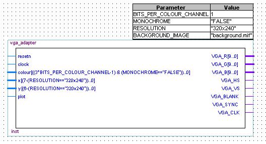
To change the VGA Adapter parameters, simply double-click on the box with parameters. This will open up a "Symbol Properties" window in which you can modify module parameters by going to the "Parameters" tab. Then for each parameter you want to change, select it from the list at the bottom of the window, modify the parameter's value and press the "change" button. Once you have modified the parameters to your liking, press the "Ok" button for the changes to take effect.
Resolution/Colour table
The following table shows parameter settings for the VGA Adapter module and the resulting number of colours and memory usage. Notice that with the increase in resolution and the number of colours, the amount of memory used increases as well. Choose your parameters according to your needs, keeping in mind that the VGA Adapter will likely not be the only component of your design that uses memory.
| Resolution | Colour Channel Depth | Monochrome | Color Range | Memory Usage (bits) | Memory Usage (%) |
| 160x120 | - | TRUE | 2 | 19,200 | 4% |
| 160x120 | 1 | FALSE | 8 | 57600 | 12% |
| 160x120 | 2 | FALSE | 64 | 115200 | 24% |
| 160x120 | 3 | FALSE | 512 | 172800 | 36% |
| 160x120 | 4 | FALSE | 4096 | 230400 | 48% |
| 160x120 | 5 | FALSE | 32768 | 288000 | 60% |
| 160x120 | 6 | FALSE | 262144 | 345600 | 72% |
| 160x120 | 7 | FALSE | 2097152 | 403200 | 84% |
| 320x240 | - | TRUE | 2 | 78600 | 16% |
| 320x240 | 1 | FALSE | 8 | 230400 | 48% |