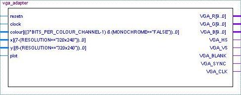
VGA Adapter's Interface
The VGA Adapter provides an easy to use interface for drawing on a screen. It takes the x and y coordinates as well as a colour of a MegaPixel to be drawn from the user. When the user sets the plot input to a logic 1, then at the next positive edge of the clock the adapter will store the new MegaPixel in its memory and draw it the next time the monitor screen is updated.
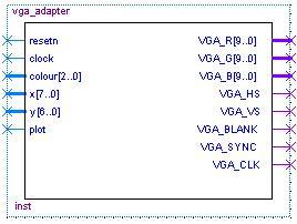
To illustrate how to use the adapter we present the following example. Suppose that you specify that the adapter is to function at a resolution of 160 by 120 MegaPixels and uses 1 bit per colour channel. Then you VGA Adapter interface would look as follows:
Now, lets try to use the adapter to draw a few pixels somewhere on the screen. For example, let us draw two pixels, one at (15, 62) and the other at (109,12). The timing diagram representing how the input signals should be set is presented below. In the diagram the first MegaPixel drawn is red and is placed at (15, 62). The second is a yellow MegaPixel being written to (109, 12). As outlined, the values for the signals (colour, x, y) are set up before and held after the positive edge of the clock.
Port Descriptions
The following table outlines the connections to the VGA Adapter module and their respective descriptions.
| Port Name | Description |
| resetn | This is an active low input port that causes the VGA Adapter to reset. Typically, this port is connected to the top-level reset signal in the design. |
| clock | This port supplies the main clock source for the VGA Adapter. To function properly, the clock frequency of this clock must be set to 50MHz. On a DE2 board such a clock is found on PIN_N2. |
| colour | The colour bus defines the color of the Mega Pixel to be drawn. In the MONOCHROME mode this bus has only one bit. If set to 1 it causes the colour of the pixel drawn to be white. Otherwise a black pixel is drawn. In a colour mode, this bus has 3*n bits, where n is the number of bits used per colour channel (BITS_PER_COLOUR_CHANNEL parameter). It is a composition of three separate busses that define the intensity of red, green, and blue colour components of a MegaPixel. The top n bits represent the red colour, the middle n bits represent the green colour, and finally the bottom n bits represent the blue colour. |
| x | These ports are used to specify the coordinates of the MegaPixel you would like to modify. In 160 by 120 resolution the values for x are (0-159), while the values for y are (0-119). In the 320 by 240 resolution the values for x are (0-319), while the values for y are (0-239). |
| y | |
| plot | If this signal is raised to high, the information from x, y and color is stored in the VGA Adapter module on the next positive edge of the 50 MHz clock. This will cause a MegaPixel to be drawn onto the screen during the next update. |
| VGA_R[9..0] | These ports are to be connected to the 10-bit DACs (Digital to Analog Converters) on the DE2 Educational Board. Once converted to analog, these signals are transmitted to the VGA monitor. |
| VGA_G[9..0] | |
| VGA_B[9..0] | |
| VGA_HS | These ports produce the horizontal and vertical sync signals for the VGA monitor. They must be connected to pins A7 and D8 respectively on the DE2 Educational Board. |
| VGA_VS | |
| VGA_CLK | This output clock signal operates at the frequency of 25 MHz. This signal is derived from the clock input of the VGA Adapter. This signal should drive pin B8 on the DE2 Educational Board in the top-level design to ensure correct operation of the VGA Adapter. |
| VGA_BLANK | This signal is always 1 and is necessary for the VGA adapter to function correctly. This output should be connected to PIN_D6. |
| VGA_SYNC | This is a syncronization signal for the monitor. This signal should be connected to pin PIN_B7 on the DE2 board. |