Lecture 4
Andreas Moshovos
Introduction to
the 68k programming model
As noted in the previous lecture we will be talking about how 68k is supposed to behave. This is the programming model, or in other words the information provided here is a set of rules that should be used to interpret the machine’s behavior. A correctly implemented 68k must abide by all these rules. That is, a programmer can view this model as a contract between them and the designer. If the programmer follows these rules then their program must behave as expected on any implementation of 68k. From the designer’s point of view this is the minimum set of guarantees that they should provide. They are free to deviate on anything else but an implementation that breaks the programming model is not a correct implementation and should not be called 68k. This model is also typically called the Instruction Set Architecture. We will return to this term later on.
General Notes
about Computer Structure and Operation:
As we discussed earlier, a simplified computer in general comprises three major parts:
1. The central processing unit or CPU or processor
2. Memory
3. Set of I/O devices
We have presented the memory behavior model in the previous lecture. We will discuss I/O devices later on. In this section of the lectures we will be concentrating on the CPU.
The CPU comprises two parts:
1. The datapath
2. The control
For the time being suffices to say that datapath is where data is stored and manipulated whereas the control is what orchestrates the datapath to perform all necessary actions. This information is provided just for reference for the time being, we will return to this issue when we discuss how to design a CPU that works.
What a CPU does:
In general terms a CPU goes through a series of steps repeatedly. These steps are:
1. Get next instruction
2. Decode (i.e., interpret its meaning) the instruction
3. Read Source Operands
4. Perform Operation (e.g., add two numbers)
5. Write Result
6. Determine which is the next instruction
All aforementioned steps together are called instruction execution. Depending on the instruction some steps may be optional (i.e., writing a result). We will see examples as we move along.
What is an
instruction?
In the previous discussion we have used the term instruction. An instruction defines an
operation that the CPU knows how to perform. For example, an instruction can be
something like “add two numbers”. Each processor has a predefined set of
instructions that it understands. The set of these instructions is part of the
programming model so it is part of the instruction set architecture.
In addition to the instructions the programming model includes additional information such as where the operands of an instruction can be, what is the address space of memory, what datatypes are supported, etc.
There is no clear rule on what should be part of the programming model. A good design principle, however, is to include the minimum possible set of rules that allows a programmer to reason about the machine. Note that anything you put into the programming model becomes part of a contract and has to be supported in all implementations.
The 68k
Programming Model
So, now we are ready to talk specifics and introduce the 68k programming model. We are not going to be able in a single or even in two lectures to exhaust this topic since the instructions are part of the model and there many of them. We will gradually introduce additional instructions over a set of lectures.
Let’s first describe 68k’s memory model. It comprises 2^32=4G addresses where each address is capable of holding a single byte. It used to be that original 68k had only 2^24=16M of addresses. Memory supports three data types as we explained before: 1. bytes = 8 bits, 2. words = 2 bytes = 16 bits, and 3. long-words = 32-bits.
All word and long word accesses must be aligned at a word granularity (i.e., address is divisible by two). The 68k will signal an error on unaligned accesses (will discuss this later on).
Besides memory the 68k and pretty much all modern processors have another set of storage locations that hold binary information. These are called registers. They are much fewer registers (e.g., less then 64 is typical) than memory locations and for this they are much faster to access than memory. (In semiconductors, the larger a memory structure, the slower it becomes.) Registers use different names than memory locations. That is they do not use memory addresses. The 68k has 16 32-bit registers that can be used for the manipulation of data. And two more special purpose registers. They are shown in the following figure:
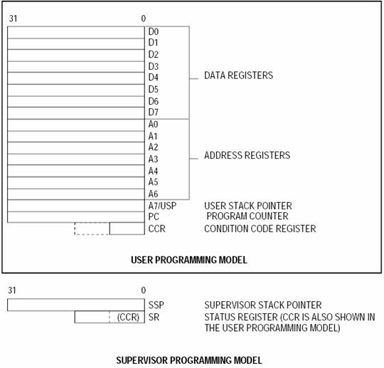
The 16 32-bit registers are separated (unfortunately) into two groups. The D and the A group, i.e., there are the D0-D7 and the A0-A7 registers. The “D” comes from “Data” and the “A” from “Address”. I find these names somewhat unfortunate as they may lead you to believe that anything stored in the D registers is just data and anything stored in the A registers is an address. This is not true. There is nothing inherent in any of these registers that will make its contents data or addresses. After all addresses are just binary information so it is “data”. In fact, the only action that makes something an address is using it to read and write from/to memory.
However, in 68k the A and D registers are different in that there are things that can be done with the A registers that cannot be done with the D registers and vice versa. These rules are part of the programming model and will be becoming accustomed to them over time.
So, we have registers D0 through D7 and registers A0-A7. A7 has special uses. It is used for something called the stack which is the key mechanism used to support subroutines. For convenience the 68k has two A7 registers. At any given point of time only one of the two is visible. Which one depends on the operating mode. There are two operating modes user and supervisor. These are added to support Operating Systems. In user mode, there are restrictions on what a program is allowed to do, while in the supervisor mode anything can be executed and accessed. In a typical computer, the OS runs in supervisor mode and hence has access to all of memory and all of the devices while user programs run in user mode and the OS can impose specific restrictions on what they can access. The ability to control access to memory and devices is a key, required mechanism for implementing operating systems. The Ultragizmo by default runs in the supervisor mode. In typical systems, the operating system runs in supervisor mode and everything else runs in user mode. We will be returning to this issue at a later time (much later time). (Whether we are in the user or supervisor mode is controlled by the second special register the Status Register (SR).)
Note that the D registers support operations on bytes, words or long words. The A registers support operations only on words or long words.
There are two special purpose registers:
1. The program counter, called PC.
2. The status register, call the SR. The SR contains the condition code register (called CCR). In user mode only the CCR part of the SR is accessible.
For the time being suffices to say that:
1. The PC is used for instruction sequencing. That it is used to identify the location of the instruction being execute and to perform step 6 of the CPU loop (determine next instruction).
2. The CCR part of the SR is used primarily in implementing control flow (instruction sequencing) decisions. It is used primarily in step 6 of the CPU loop. There are other uses of the CCR which will be explained over time.
3. The rest of the SR is used to support operating system tasks and I/O device interactions. We will explain this later on.
We should emphasize that there is nothing inside the registers that signify the use of the binary quantify they are holding. It is us that decide what these quantities mean. To the computer they are just binary quantities that can be manipulated in specific ways using instructions. And again, there is nothing that differentiates the contents of register as an address. Only if those contents are sent to memory for reading or writing then they are *used* as an address.
Our first 68k
program
As we saw before, the CPU loop amounts to executing instructions continuously. Before explaining how this is done let’s look at a simple program. For the time being we will not be concerned with how the program gets represented inside the machine or how it is executed. We will write a set of instructions and explain what the expected outcome should be. Once this is understood we will then explain where these instructions are stored, how they are sequenced and finally how they are represented.
Our first program will be the equivalent of the following pseudo-C code:
unsigned int a = 0x00000000;
unsigned int b = 0x11223344;
unsigned int c = 0x22334455;
a = b + c;
This code adds two 32-bit variables (b and c) and places the result into a third variable a.
While in C there is no implication of where the values are stored (C does not care) in a real machine the variables will have to be stored either in memory or in registers (there is nowhere else to store them). The compiler makes the decision on where to allocate each variable (if you want to force the compiler to allocate the variables in memory you can use add the keyword “volatile” before each declaration). For our purposes let’s assume that the variables are in memory, one after the other, starting at location $30000 (this address is valid for the ultragizmo).
So the relevant part of memory will look as follows:
|
Address |
+0 |
+1 |
+2 |
+3 |
|
$30000 |
$00 |
$00 |
$00 |
$00 |
|
$30004 |
$11 |
$22 |
$33 |
$44 |
|
$30008 |
$22 |
$33 |
$44 |
$55 |
“a” is in memory locations $30000 through $30003, “b” is in $30004 through $30007, and “c” is in $30008 through $3000b.
In general, many 68k instructions take the following symbolic form:
Operation.datatype Source2, Dst
For example:
add.l d0, d1
adds the contents of registers d1 and d0 and places the result in d1. Because of the “.l” suffix this is done using all 32-bits. We will use the notation d1 = d1 + d0 for this operation. We’ll use [X] to represent an access to memory. So, [100] refers to the contents to memory address 100. [100] = 10 changes the contents of memory location 100 to be the number 10, while d0 = [100] copies the contents of memory address 100 into register d0. Similarly, d1 = [a0] means read the value in register a0, use that as an address and read a value from memory, copy that into d1.
We are now ready to write our full program:
move.l $30004, d0
move.l $30008, d1
add.l d1, d0
move.l d0, $30000
Let’s explain each instruction:
1. move.l $30004, d0: This does d0 = [$30004]. That is, read (load) the 32-bit quantity stored in memory starting from address $30000 and store the result in register d0. So, this essentially reads variable b from memory into register d0. So, once executed we will have that d0 = 0x11223344.
2. move.l $30008, d1: similarly this reads c into register d1. Once executed we will have d1 = 0x22334455.
3. add.l d1, d0: d0 = d0 + d1, or essentially d0 = b + c. Once executed, d0 = 0x33557799.
4. move.l d0, $30000: [$30000] = d0. This is a write (store) to memory. The value written is a long-word and it is written to locations $30000 through $30003. This is where a lives in. Once executed [$300000] = 0x33, [$30001] = 0x55, [$30002] = 0x77, and [$30003] = 0x99. We will use the shorthand notation [$30000] = 0x33557799 from now on.
This is not the shortest possible program for performing the desired computation. Unfortunately, when 68k was designed the technological tradeoffs and the mindset of computer designers was such that they believed that designing “powerful” instructions was a good thing. Many of the decisions they made were influenced in large part by a desire to keep implementation feasible given the relatively few transistors that were available for a CPU and a desire to provide powerful instructions that are as close as possible to high-level programming constructs. This is not what most designers believe is a good design methodology now days but remember it is always “easy” to look in the past and criticize when new information becomes available. To their defense, the 68k designers came up with one of the simplest instruction sets at the time.
So, alternatively we could write:
move.l $30004, d0
à
d0 = [$30004] = 0x11223344
add.l $30008, d0 à
d0 = d0 + [$30008] = 0x11223344 + 0x22334455 = 0x33557799
move.l d0, $30000 à
[$30000] = d0 = 0x33557799
Note that the second instruction now has one of its operands in memory. So, it replaces two instructions of our original program. It performs both a memory read (load) and an addition. You can view it as the equivalent of:
tmp = [$30008]
d0 = d0 + tmp
where tmp is some temporary storage register inside the 68k that is not visible to the programmer.
Addressing Modes
As we mentioned earlier, many 68k instructions take the following form:
Operation.datatype Source2, Dst
There are several ways of specifying the two operands Source2 and Dst. Thus far we have seen two: (1) a memory address as in $30008, and (2) a register identifier. There are other possibilities. Each way of specifying an instruction operand is called an addressing mode. The name is somewhat unfortunate as it may incorrectly lead someone to believe that they necessarily refer to ways of referencing memory. This is not true. “Operand mode” may have been a better term. So, in summary there are several ways of referring to instruction operands which are called addressing modes. They may be ways of referring to data stored in memory, or they may refer to registers or constants. Other possibilities exist.