Lecture 5
Andreas Moshovos
Stored Program and
Instruction Representation
In the previous lecture we have seen an example of a 68k program. We have intentionally avoided to discuss where this program exists inside the machine, how instructions are represented and how the CPU sequences through them. These will concern us in today’s lecture.
The 68k very much like any other processor uses the concept of a stored program. That is the instructions that comprise the program we want to execute are represented using binary numbers and are stored inside the memory. So, inside a computer instructions as expected are too represented using a collection of bits. They are also stored in memory very much like anything else inside the computer. How does the CPU know if something is an instruction or not? It does not. Any memory location may potentially contain data or instructions. What differentiates the two is not to be found in memory itself. The only thing that differentiates an instruction from data is the point in time the CPU references it. Recall that a CPU goes through the following steps repeatedly:
1. Get next instruction
2. Decode (i.e., interpret its meaning) the instruction
3. Read Source Operands
4. Perform Operation (e.g., add two numbers)
5. Write Result
6. Determine which is the next instruction
What makes some memory contents an instruction is that it they are referenced in step 1. Similarly what makes some memory contents data is that they are not referenced in step 1 (in our description such data will be referenced in steps 3 and 5 but depending on the processor and the instruction the number of steps we described may not be a good match with what the processor actually does).
In 68k we can refine the description of the CPU execution steps as follows:
1. Get the instruction from the memory location pointed to by the contents of PC
2. Decode. Repeat step 1 as needed by the instruction (we will explain this later on).
3. Read Sources
4. Perform Operation
5. Write Result
6. Alter PC so that it now points to the next instruction we want to execute
As you can see now step 1 is described in more detail. Instructions are stored in memory and the contents of the PC register are used as the starting address from where the next to be executed instruction is read. Because the length of an 68k instruction is bytes can vary decoding and reading the instruction from memory (steps 1 and 2) is an iterative process. We will explain these combined steps later on.
Step 6 which is “determine what is the next instruction” is implemented by changing the value of the register PC. This way, when we return to step 1 for the next instruction, the PC should be pointing at the address where the bytes representing this next instruction are stored.
It is important to emphasize that any memory location can hold data or instructions and that both are just binary quantities. There is nothing in memory that differentiates instructions from data. If a memory access is done at step 1 then the binary quantity read will be interpreted as an instruction otherwise it will be used as data by the current instruction.
Let us now return to our example program and explain how it is represented in memory. A bit of warning here: The representation used by 68k is not very simple. There are machines that use more complex representations, but many of the newer CPUs (those designed since the late 80’s) use much simpler ways of representing instructions. At the time 68k was designed, there were significant restrictions imposed for technological reasons (there were few transistors in a single chip) moreover, most instruction sets were being designed to implement as many high-level programming constructs directly in hardware as possible. So, the encoding of 68k instructions may seem unnecessarily complicated. This is indeed true today but it was not so at the time it was designed and understanding every single decision is non-trivial and requires a lot of effort which is not necessarily time well spent.
Here’s the way our program is represented in memory, assuming that the instructions start at address $10000:
|
|
|
|
|
$10000 |
$20 |
move.l $00020004, d0 |
|
$10001 |
$39 |
|
|
$10002 |
$00 |
|
|
$10003 |
$02 |
|
|
$10004 |
$00 |
|
|
$10005 |
$04 |
|
|
$10006 |
$d0 |
add.l $00020008, d0 |
|
$10007 |
$b9 |
|
|
$10008 |
$00 |
|
|
$10009 |
$02 |
|
|
$1000a |
$00 |
|
|
$1000b |
$08 |
|
|
$1000c |
$23 |
move.l d0, $00020000 |
|
$1000d |
$c0 |
|
|
$1000e |
$00 |
|
|
$1000f |
$20 |
|
|
$10010 |
$00 |
|
|
$10011 |
$00 |
In our example code every instruction is represented using 6 consecutive bytes. The first two bytes are mandatory for all 68k instructions and contain information that identifies the operation and the form of the operands. At the very minimum a 68k instruction will use just those two bytes. We will explain in some detail the encoding used in those two first bytes. Depending on the information contained there additional bytes may follow. If you notice in all three of our instructions one of the operands is an address. Our addresses are such that they cannot be represented using just a word. Thus, they are presented using the long word datatype. Moreover, the exact numeric value corresponding to each address is encoded in the four bytes that follow each instruction. For example, notice that the bytes at locations $10002 through $10003 if assembled into a long word form the value $00020000 (which is the same as $20000 but recall that inside a computer we have fixed width representations).
Let’s look at the first instruction:
|
$10000 |
$20 |
move.l $00020004, d0 |
|
$10001 |
$39 |
|
|
$10002 |
$00 |
|
|
$10003 |
$02 |
|
|
$10004 |
$00 |
|
|
$10005 |
$04 |
The first two bytes encode the following information:
1. This is an add operation
2. This should be done using long words
3. The destination/source 1 is register d0
4. The second source operand comes from the memory location $00020004
When the designers of the first 68k decided on the encoding to be used what they did is they wrote down all possible combinations of operations, datatypes and operand specifiers and then designed an appropriate encoding that was simple enough to implement, matched well with the technological constraints of the time and more important was capable of representing every single instruction. The 68k has 56 operations, it has 14 different ways of reference to source or destination operands and various ways of combining source and destination operands. The set of possibilities is high enough that it is not practical (and not very educational either) to attempt to explain all encodings. Accordingly, we will restrict this discussion to a couple of examples. The book has an appendix where it explains all possible encodings. Use it as a reference.
Returning to the first instruction, let’s look into the first two bytes in detail:
Encoding of
“move.l $20004, d0”:
The value stored is in binary:
0010 0000 0011 1001 = $2 0 3 9
MOVE instructions use the following groups of bits
00SS RRRM MMmm mrrr
That the first two bits are zero signifies a MOVE instruction.
The next two bits SS encode the datatype being move. SS=10 is used for long word. Note that two bits are used since there are three possible datatypes. So, since with two bits we can encode four things, two bits are sufficient to specify any of the possible datatypes.
The MMM bits (M from mode) are used to encode the way this instruction refers to its destination/source operand. The value MMM = 000 is used to signify a data register (we will see that there at least 12 different ways of specifying this operand). Given that MMM is 000 then the RRR field provides the name of the D register being specified. Since the instruction uses d0 these bits take the value 000 (had we used register d6 these bits would have the value 110).
The next six bits (mmm rrr) encode the second operand (the source2) which for us is a long word address.
The combination mmm rrr = 111 001 is used for long word addresses that are encoded in the instruction itself. This is called “absolute long address”. Once 68k sees this pattern there then it will read the four bytes that follow and treat them as a long word that is the address where the second operand is stored. This is why the four bytes that follow form the long word $20004.
In summary the encoding of the first two bytes of move instructions is as follows:
Encoding of “add.l
$20008, d0”:
|
$10006 |
$d0 |
add.l $00020008, d0 |
|
$10007 |
$b9 |
|
|
$10008 |
$00 |
|
|
$10009 |
$02 |
|
|
$1000a |
$00 |
|
|
$1000b |
$08 |
The value stored in memory for the first two bytes is (recall that an instruction is at least two bytes long):
1101 0000 1011 1001 = $d 0 b 9
Notice that first two bits are not 00 as they were for the move instruction. This way the 68k can differentiate between move and some other instruction. This is necessary, otherwise it would be impossible to differentiate between a move and an add.
The encoding of the ADD instruction uses the following bit groups:
1101 DDD0 SSmm mrrr
The ADD instruction is encoded by using the value 1101 for the four most significant bits.
The DDD bits encode the register number of the D register being used as a source/destination. They are 000 in our case since we use d0.
The next bit is 0 signifying that this instruction has a source/destination operand that is a D register.
The SS bits encode the datatype operated on. SS=10 means a long word.
The last six bits encode the second source operand. Notice that mmm rrr = 111001 which as we have seen in the move instruction signifies a long word absolute address. So, for this reason the 68k will read the next four bytes and used them as an address in memory where the second source operand lies in. This is why the next four bytes form the long word $20008.
Encoding of
“move.l d0, $20000”:
|
$1000c |
$23 |
move.l d0, $00020000 |
|
$1000d |
$c0 |
|
|
$1000e |
$00 |
|
|
$1000f |
$20 |
|
|
$10010 |
$00 |
|
|
$10011 |
$00 |
The value stored in memory for the first two bytes is (recall that an instruction is at least two bytes long):
0010 0011 1100 0000 = $2 3 c 0
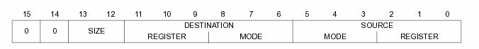
The first two bits are 00 hence this is a move instruction. The encoding uses the following bit groups:
00SS RRRM MMmm mrrr
SS is 10 hence this operates on long words.
The RRRMM encode the destination operand. We have RRR=001 and MMM=111. This signifies a long word operand. Notice that MMM is not 000 as it was when RRR was used to encode a D register name. This way the 68k can differentiate amongst different ways of referring to operands. Because the destination/source operand is a long word absolute memory address, the 68k will expect that the next four bytes in memory form the exact address. This is why the last four bytes form the value $20000.
The last six bits are mmm rrr = 000 000. Because mmm is 000 then this is D register and its name is given by the rrr bits. The rrr bits are 000 because this is register d0.
General
Observations about Instruction Encoding
When the 68k designers were deciding about the 68k instruction encoding they operated under a set of requirements and a set of desirable properties:
1. REQUIREMENTS:
The encoding should be such that it can uniquely encode all possible (valid) combinations of:
a. Operation (e.g., add and sub)
b. Datatypes (e.g, word, long-word)
c. Operands for src2 and src1/dst
The encoding must be reversible. That is it should be possible given an textual representation of
an instruction (add.l d0, d1) to determine its encoding in binary and then it should be possible given
a binary encoding to determine what is the instruction this corresponds to.
2. DESIRABLE PROPERTIES:
a. The amount of memory required to represent a program should be as small as possible.
b. It should be as easy as possible to decode an instruction.
To satisfy 2.a the 68k designers used a variable length instruction encoding. That is instructions do not use the same number of bytes for their representation. There are at least two bytes but there may be more.
There are other CPU families that use a fixed length instruction encoding where all instructions use the same number of bits for their representation.
As an example of how encoding can be done assumed that we are asked to come up with encoding for a machine that has: 32 Registers each of 4 bytes, 16 different operations, 1 possible datatype (4 bytes) and instructions of the form dst = src1 OP src2 where dst, src1 and src2 are registers (we would need other instructions for accessing memory and sequencing but for clarity and without loss of generality let us assume that these are the only instructions that this machine has). How can we encode these instructions?
There are many different ways. Here’s one.
1. How many bits do we need to encode the operation? Since there are 16 operations 4 bits should be sufficient. So, let’s use the four most significant bits for this purpose. We then we have to come up with a mapping of four bit binary quantities and operations. For example, we could define that 0000 is for an addition, 1000 is for subtraction and so on. Any encoding is valid.
2. Besides the operation we should be able to specify the datatype. Since there is only one datatype we do not need to directly encode this using bits. This can be implied.
3. Finally, we need to encode the three operands. We assumed that these refer to registers. There are 32 registers, let’s call them X0 through X31. To refer to each one of those 32 registers a five bit name is sufficient. That name can be made to encode the binary form of the register number (n in Xn). Since there are three operands, we will need three five bit names.
Our encoding can then be:
|
4 bits |
5 bits |
5 bits |
5 bits |
|
OPERATION |
DST |
SRC1 |
SRC2 |
As an example, let’s see how we would then encode ADD X1, X15, X31
The encoding will be:
0000 00001 01111 11111
the first four bits (0000) stand for ADD
the next five are for the destination register X1
the next five are for the first source register X15
and the last five are for the second source register X31.
Instruction
Sequencing:
Having seen an example of how instructions are encoded in memory let us now see what the 68k does to execute our program. The CPU loop now becomes:
1. Read/Decode instruction
a. Read two bytes from memory using the PC value as the address to start reading from
b. Depending on what is contained in those two first bytes, read any subsequent bytes as required (four in our example for the absolute address operand)
2. Read source operands (data)
3. Perform operation
4. Write result to destination
5. PC = PC + sizeof(instruction)
Where with sizeof(instruction) we refer to the number of bytes read in step 1.
What we described is straight line execution. That is, once an instruction is executed, then the next (“following line” on paper – “following address” in memory) will be executed.
For our example program sizeof(instruction) is always 6. However, this is not always the case as different instructions may require different number of bytes to be represented (at least two bytes are needed).
In the next set of lectures we will be looking at control flow (other than straight-line instruction sequencing) and at different ways of referring to source and destination operands.
How it all starts?
As long as instructions and data are in memory everything works just fine. For example, we can write a program that allows us to load other programs in memory and thus run any program we would like. But how do we get to execute the first instruction/program? This is the RESET sequence. In 68k the first two words in memory are special. The contain an initial value for the PC and the A7 register (PC would have been enough).
When power comes on, the 68k first loads the PC with the corresponding value and then starts reading and executing instructions for that address. How do we get to set this initial address and the instructions plus data that will be executed? In the ultragizmo part of the memory is assigned to ROM devices. These are memory devices whose contents are fixed. ROM devices have values already in them and actually we cannot change them.