Lecture 10
Andreas Moshovos
Spring 2005
Binary Manipulation
Instructions:
Thus far we have seen instructions that move data (from/to
memory or registers), calculate arithmetic functions (add, sub) or that change
the control flow. There are other
classes of instructions in 68k that are also commonly found in most modern
processors. The first class of instructions we will discuss, implements bit-wise boolean logic operations. The
second class operates on single bits.
The third class performs shifts and rotates.
Bitwise Boolean Logic
Instructions
As an example let’s consider the AND.L instruction. All bitwise instructions treat their arguments as a collection or 32 independent bits (or 16 bits or 8 bits) without assigning an arithmetic value to the collection. For them, a register or a memory value is just an ordered collection of 32 bits (or 16 or 8 – OK I’ll stop saying this from this point on, but please do recall that the following discussion applies to words and bytes also). They then operate on each of those 32 bits separately.
So, AND.L D0, D1 performs 32 boolean AND calculations in parallel. Each of those 32 AND calculations is done using two bits, one from the D0 register and one from the D1 register. The bit 0 of D0 is used with bit 0 of D1, bit 1 of D0 is used with bit 1 of D1 and so on. Each of two 32 bit pairs produces a result which is written into the corresponding bit position in the destination register. That is, the result of (bit 0 of D0 AND bit0 of D1) is written into bit 0 of D1.
As an example assume the following initial values of D0 and D1:
3 2 1
1 3 5 7 0
D0 = 00000101 11111111 11001100 00110011
D1 = 11111100 00000111 00111001 00010010
------------------------------------------------------
D1 00000100 00000111 00001000 00010010 <--
AND.L D0, D1
Note that this is equivalent to the “&” operation in C. The “&&” operation in C operates on TRUE and FALSE values (non-zero and zero respectively in most C dialects – some define <= 0 as false).
These operations are called bitwise because they treat
their operands as a collection of bits that are operated upon individually.
Note on word and byte bitwise calculations: We can operate on longwords, words or just bytes. When operating using words, the upper two bytes of the destination register are left untouched. Similarly, when operating on bytes, the upper three bytes of the destination register are left unchanged.
For the AND instruction one of the two operands must be a D register.
AND with Immediate: There is a variation where the source operand can be an immediate. This is the ANDI instruction. For example we can use AND.L #$0000ffff, D0 to set the upper two bytes of D0.
AND operations are useful among other things for masking out bits out of long values. For example, say we are interested in whether an integer is even. In this case, the lower bit of the integer must be 0. Accordingly we can use the following sequence:
ANDI.L #1, D0
BEQ ISEVEN
By “masking out” we mean isolating the value of a bit or a collection of bits.
AND can also be used to set specific bits to 0. For example, let’s say that we want to make bit 3 of D0 zero. Here’s how:
ANDI.B #%11110111, D0
Note that all but the bit we are interested in are set to 1 in the immediate.
Also note that ANDI.L #%111, D0 is equivalent to (D0 MOD 8). Similarly, ANDI.L #%1111 1111 1111 1111 1111 1111 1111 1000, D0 is equivalent to (D0/8)*8 in integer arithmetic.
What we have done is use a constant that had a 1 only at the bit position that we were interested in. By doing a logical AND with this constant we essentially zeroed out all bits except the last one. As a result, the outcome of the AND operation would be zero if the least significant bit was zero otherwise it will be non-zero.
Such operations are very handy when accessing data that uses long datatypes to encapsulate a collection of different information pieces. This we have seen when we discussed I/O devices.
Other bitwise logical operations are:
EOR and EORI = exclusive OR (XOR), result is 1 if the two input bits have different values. In C xor is “^”.
e.g., EOR (A0), D0 à [d0] = [d0] XOR MEM[[A0]]
OR and ORI = OR. In C or is “|”.
e.g., OR D1, D0 à [d0] = [d0] OR [d1]
NOT: This in C is the “~” operation.
e.g., NOT D0 à [d0] = reverse of [d0] (i.e., 1s changed to 0s and vice versa).
The following table summarizes these instructions:
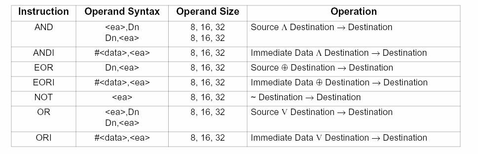
Where EOR is the Exclusive OR, or also called XOR. So 0 EOR 0 = 0, 0 EOR 1 = 0, 1 EOR 0 = 1, and 1 EOR 1 = 0.
As a side note, here’s a quick way to swap the values of two registers:
eor.l d1, d0
eor.l d0, d1
eor.l d1, d0
If you have not seen this before try to figure out how it works? Try a couple of examples, then try to express the outcome of each instruction as a function of the original values of d0 and d1 and XOR. Keep in mind that A XOR A = 0, A XOR 0 = A and A XOR 1…1 = not(A). Some machines provide a swap instruction.
The C equivalents of the aforementioned bitwise operations are:
1. a AND b à a & b
2. a OR b à a | b
3. a EOR b à a ^ b
4. NOT a à ~a
Using OR we can set specific bits to 1. For example, ORI.B #%1000, D0 sets bit 3 to 1.
Using EOR we can “flip” the value of bits. For example EORI.B #%100, D0 changes the value of bit 2 to its opposite (a 1 becomes a 0 and vice versa).
These operations are quite useful for graphics applications where screen pixels are represented as bits in memory.
Single Bit
Manipulation Instructions:
These instructions change the value of a single bit. Before doing so they copy the value of this bit into the Z condition code.
BCLR.datatype bitno, destination
BCHG.datatype bitno, destination
BSET.datatype bitno, destination
BTST.datatype bitno, operand
The first three respectively clear, reverse and set the (bitno) bit of the destination. Before changing the bit value, the bit is copied into the Z condition code. The last instruction simply does that and does not affect the operand (tests for a bit value).
Examples:
BCLR.L #0, D0 à clears bit 0 (least significant of D0)
BSET.B #7, D1 à clears the 8th bit of register D1
Bits are numbered starting from 0 (leftmost – least significant). The datatype can be either a byte or a longword.
The following table summarizes these instructions where Z is the Z condition code flag in register SR. “~” means NOT as it also does in C.
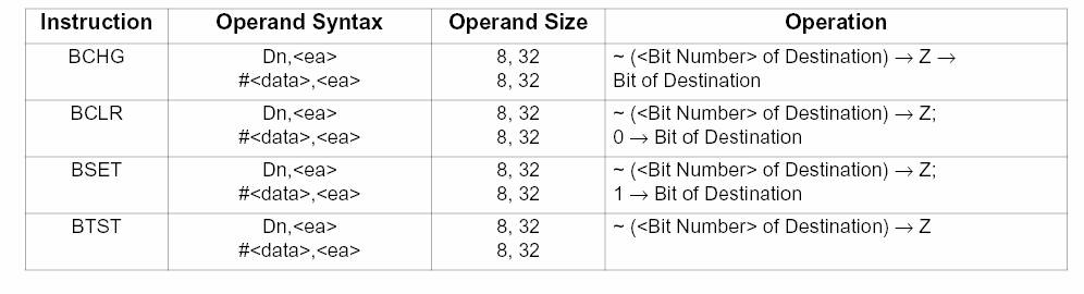
As practice, synthesize the behavior of each of the bit instructions using the AND, OR, EOR and NOT instructions instead.
Shifts:
The third class of bit manipulation instructions treats their operands as series of bits placed one after the other. They displace these bits by a number of positions. Lets us look at each one of these instructions. The shifts correspond to the “>>” and “<<” operations in C. There are no C equivalents for the rotate instructions (although we can synthesize them using shifts and bitwise logical operations).
First are logical shifts. For clarity we will restrict our attention to the 8 bit datatype however the discussion applies to all three datatypes.
Logical shifts can be performed either to the left or to the right. In shifts, the bits of the operands being shifted are treated as 8 bits placed in order one after the other and on a straight line. The instruction shifts those bits either to the left or to the right by a number of bit positions. The positions that are left empty are filled with zeroes and the bits that are shifted out of limits are simply discarded.
The two instructions are:
LSL.datatype n, operand à shift left the operand by n bits
LSR.datatype n, operand à shift right the operand by n bits
Consider for example a logical shift left:
lsl.b #1,d0
Assume that initially the value of the lower byte of d0 is 11001101. Shifting left by one position gives 10011010. Note the 1 that was at the most significant bit position in the source operand was discarded and the empty position that was created by shifting the bits to the left was filled with a 0.
lsl.b #4, d0 will give 11010000.
lsl.b #6,
d0 will give 0100000.
Similarly for logical shifts to the right we have:
lsr.b #1, d0 will give 01100110 (the last bit of the source operand was discarded)
lsr.b #5 d0 will give 00000110.
In summary, logical shifts move the bits by a specified number of bit positions to the left or right. Bits positions that are emptied are filled with zeroes and bits that are moved out of the bit positions that are available in the datatype are discarded.
Relation of Shifts with Division and Multiplication: If the operand being shifted is interpreted as an unsigned integer then shifting left by 1 bit is equivalent to multiplying the operand by 2. Similarly shifting right by 1 bit is equivalent to dividing by 2. It follows that:
1. Shifting left by n bits is equivalent to multiplying by 2^n
2. Shifting right by n bits is equivalent to dividing by 2^n
Arithmetic Shifts: The second class of shifts is meant to be used for quantities that are presumed to be signed integers (2’s complement). The two instructions are:
ASL.datatype n, operand à Arithmetic shift left
ASR.datatype n, operand à Arithmetic shift right
Arithmetic and logical shifts to the left are equivalent except in that they update the condition codes differently (ASL also sets the overflow flag if at any time during the shift the most significant bit is set to 1, LSL sets V to false). The right shifts, however, differ significantly. While the logical fills in the emptied bits with zeroes, the arithmetic shift fills them with the most significant bit of the source operand.
For example, assume D0 = 1101 0010 and D1 = 0101 0011 then:
ASR.B #3, D0 à will produce 1111 1010
LSR.B #3, D0 à will produce 0001 1010
ASR.B #2, D1 à produces 0001 0100
LSR.B #2, D1 à produces 0001 0100
Arithmetic shifts to the left and to the right by n bits are equivalent respectively to multiplying or dividing by a power of 2 with one exception: if the operand is -1 then the arithmetic shift right does not produce 0 as it should. It produces -1 (note -1 is represented as all ones).
ROTATES:
The last class of bit manipulation instructions treats their source/destination operand as a sequence of bits that are placed on a circle. That is the bits are ordered (bit 1 is next to bit 2 which is next to bit 3 and so on) and bits 0 and 7 (for byte instructions) are also adjacent.
The two instructions are:
ROR.datatype n, operand à rotate the operand to the right by n bits. To the right means towards bit 0.
ROL.datatype n, operand à rotate the operand to the left by n bits.
So, assuming that the least significant byte of D0 is 01101101 then we have:
ROR.B #1, D0 à produces 10110110
ROR.B #2, D0 à produces 01011011
ROR.B #3, D0 à produces 10101101
Similary:
ROL.L #1, D0 à produces 11011010
ROL.L #2, D0 à produces 10110101
ROL.L #3, D0 à produces 01101011
There two variations in which the X condition code participates in the rotate as one of the bits. In this case the X bit appears in between the first and the last bits (bits 0 and 7 for bytes, bits 0 and 15 for words and bits 0 and 31 for long words).
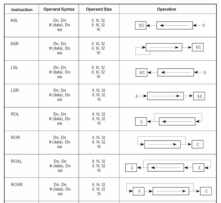
The following table summarized all shifts and rotate instructions:
Synthesizing
Multiplication Using Shifts and Additions
Multiplication is a commonly needed calculation. Multipliers, however, are relatively expensive circuits and/or slow. For this reason but also as means of getting familiar with shifts we now explain how multiplication can be implemented using just left shift and addition instructions. At a high level, the key idea is to convert multiplication into a sum of multiplications with just powers of two. This is easier understood using an example. Assume we want to multiply the value in register D0 by 5. One alternative would be to add the value in D0 five consecutive times. This quickly becomes impractical (for example, to multiply by 1000 we would need 1000 additions). An alternative is to analyze the multiplier to a sum of powers of 2. So, 5 becomes (4 + 1). In turn 5 X D0 becomes 4 X d0 + 1 X d0. Similarly, 11 x d0 can be rewritten as 8 x d0 + 2 x d0 + 1 x d0. The nice thing about using powers of two is that the corresponding multiplications can be implemented via simple left shift instructions.
Here’s the code for multiplying d0 by 11 with the result stored in d1:
move.l d0, d1 ; make a copy of d0 in d1, so now d1 = d0 x 1
lsl.l #1, d0 ; d0 = d0 x 2
add.l d0, d1 ; d1 = d0 + d0 x 2
lsl.l #2, d0 ; d0 = d0 x 4 but since we changed d0 to 2 times its original value, now d0 is 8 times its original value
add.l d0, d1 ; d1 = d0 + d0 x 2 + d0 x 8
Here’s the code for multiplying d0 by 17:
move.l d0, d1 ; d1 = d0
lsl.l #4, d0 ; d0 = 16 x d0
add.l d0, d1 ; d1 = d0 + 16 x d0
In general, if we need to calculate A x B then look at the binary representation of B focusing on the bits that are 1. If B’s binary representation has a 1 at bit i, then we need to include A x 2^i into our sum. So, if B = 10101 the sum will include the following terms: A x 2^0, A x 2^2 and A x 2^4.
Synthesizing
Multiplication Using Shifts, Additions and Subtractions --- Booth’s Algorithm
In our previous discussion we only used shifts and additions. What if we were also allowed to use subtraction? Can we perform multiplication in fewer steps?
Yes, we can here’s an example why: Assume that the multiplier is 01110011110 in binary. Let’s rewrite this as 01110000000 + 00000011110, where we separated the two streaks of 1’s.
Now notice that A x 01110011110 can be rewritten as A x 01110000000 + A x 00000011110. With the previous method (adds and shifts) we will need three shifts for the first term, four shifts for the second term and so on. In addition we will need several additions to sum all these together.
Before proceeding with the example it is going to be helpful to realize that any binary number of the form 0..01..10..0 (where the 0…0 parts are optional), that is any number where all bits that are 1 form continuous sequence, can be rewritten as a difference of two binary numbers each with a single bit set to 1. For example, 011 = 100 – 001, 0110 = 1000 – 0010, 01111 = 10000 – 00001 and 0011000 = 0100000 – 0001000. In general if we have a number of the form 0…01…10..0 where the leftmost 1 is at position L and the rightmost 1 is at position R (where bit positions are numbered right to left, starting with 0) the number can be rewritten as (A – B) = (0…010…0 – 0…010…0) where the 1 in A appears at bit position L+1 and the 1 in B appears at position R.
So returning to our example, we had A x 01110011110 = A x 01110000000 + A x 00000011110.
But, 01110000000 can be further rewritten as (10000000000 - 00010000000), so A x 01110000000 can be written as A x 10000000000 – A x 00010000000. The last expression requires just two shifts and one subtraction.
Similarly, A x 00000011110 can be rewritten as A x 00000100000 - A x 00000000010. For this calculation we need just two shifts and a subtraction.
In summary A x 01110011110 can be calculated as (A x 10000000000 – A x 00010000000 + A x 00000100000 - A x 00000000010)
In general, if we need to calculate A x B we write B in binary and then starting from the rightmost bit and moving towards the left we do:
1. result = 0
2. If the current bit at position i is 0, move to the next bit (i = i + 1) and repeat this step, else result = result - A x 2^i and move to step 3.
3. If the current bit at position i is 1, move to the next bit (i = i + 1) and repeat this step, else result = result + A x 2^i and move to step 2.
This algorithm is known as Booth’s Algorithm for multiplication. The reason we discuss this algorithm is that it is important to know that further optimizations may be possible when doing arithmetic or other operations. So, when designing circuits or algorithms to perform these operations it is always important to check what is the best algorithm that exists and that better matches your problem (certain things are faster/preferable in hardware than in software and vice versa).