Lecture 16
Andreas Moshovos
Input/Output
Devices Continued: The Serial Interface (UART = Universal Asynchronous Receiver
Transmitter)
In previous lectures we have seen the Parallel Interface device that provides a number of external connections that can be accessed in parallel (simultaneously as a group).
The parallel interface device required not means of synchronization when reading or writing from/to it. That is, we assumed that all transactions completed instantaneously.
In this lecture we will discuss another device, the serial interface where transactions are not instantaneous. Instead, it will take time for the serial device to complete a request of ours. This will allow us to discuss a new topic that relates to I/O devices: synchronization. We will first explain the programming interface of the UART device and then discuss about how it actually communicates with external devices.
The UART device:
The Ultragizmo board includes a two port serial device called a DUART (i.e., Dual UART). You have been using Port A for interacting with the Ultragizmo. Port B is available for experimenting by communicating with the PC. The receiver can be used to receive characters from the PC’s keyboard while the transmitter can be used to send character to the PC’s display. We will restrict our attention to Port B but please note that Port A is almost identical (only the memory addresses used for the registers change). The actual DUART interface contains several additional registers which we will not cover. These registers control various aspects of the communication such as its rate, data types, etc.
The Port B UART interface comprises the following memory mapped registers:
1. Status Register, SRB at location $fffff7f3
2. Receiver Buffer, RBB at location $fffff7f7
3. Transmitter Buffer, TBB at location $fffff7f7 (not a typo, it *is* the same address as the RBB).
There are two transactions (i.e., operations) that can be asked of the UART: (1) send a character, or (2) receive a character. In a typical, setting the UART is connected via a few wires with an external device that is also capable of sending and receiving characters (such as the PC in the lab). The RBB and TBB are used respectively for receiving or sending characters (let us assume that characters are 8 bit for simplicity, but please note that there is another control register in the DUART that can be used to configure different bit lengths for characters). They both map onto the same memory address. When reading from this memory location we are accessing the RBB, while when we write into this memory location we are accessing the TBB.
The status register is necessary for the following reasons:
1. Sending characters takes considerable time compared to the CPU’s processing speed (several thousand CPU cycles). Hence, we must be able to wait until the UART is sending a character before we attempt sending another one.
2. We should read a character from TBB only if one has been received from the external source.
Accordingly, the Status register exists to provide information about (1) and (2). The status register has the following format:
|
|
7 |
6 |
5 |
4 |
3 |
2 |
1 |
0 |
|
|
Status Register |
|
|
|
|
|
TxRdy |
|
RxRdy |
|
The bits of interest are bits 0 and 2, or RxRdy and TxRdy respectively. RxRdy is 1 when the receiver has received a character. Accessing the RBB clears this bit effectively indicating that we consumed the character. Once a new character is received from the external device, the RxRdy is automatically set to 1.
The TxRdy is 1 when the transmitter is available for sending a character. If it is 0, then it is busy sending a character. While it is busy we should not access TBB as this will have unspecified results.
Here’s a subroutine that accepts a character from the UART:
SRB equ $fffff7f3
RBB equ $fffff7f7
TBB equ $fffff7f7
org $20000
getchar
btst.b #0, SRB
beq getchar ; while bit 0 is 0 keep probing the SRB
move.b RBB, d0 ; read character into d0, this resets bit0 of SRB
rts
And here’s one that sends a character:
SRB equ $fffff7f3
RBB equ $fffff7f7
TBB equ $fffff7f7
org $20000
putchar
btst.b #2, SRB
beq putchar ; while bit 0 is 0 keep probing the SRB
move.b -4(a7), TBB ; send character, this sets bit1 of SRB
rts
(note that the sequence:
loop btst.b #0, SRB
beq loop
is preferable over:
loop move.b SRB, d0
and.b #1, d0
beq loop
)
In both subroutines we use a busy-wait loop where we continuously probe the SRB until the receiver or the transmitter become available. Such loops are called busy-wait as the processor remains busy (i.e., executes instructions that communicate with the device) while not doing any productive work as it is simply waiting for the device to become available. This style of communication with devices is called POLLING. In polling we continuously probe the device until it becomes available or it completes our request. Polling is simple, but uses processor resources ineffectively. Using polling becomes at least cumbersome when more than one devices are involved as we have to write our code in a way that continuously probes several devices. In some cases, it is simply inappropriate. For example, consider what would happen if windows or X windows used polling for accepting input from the mouse: everything would freeze until you moved the mouse and then freeze again if you stopped moving it.
In real life, polling would be the equivalent of handing a piece of work to someone else and then keep knocking on their door asking: “Are you done yet?” There is an alternative, which requires additional support at the hardware level. We will cover the alternative in a later lecture. It corresponds to the real life scenario where you hand out a task and then do something else while expecting to be notified when the task is completed.
As a final example, we present the echo routine, it just repeats the characters it receives:
SRB equ $fffff7f3
RBB equ $fffff7f7
TBB equ $fffff7f7
org $20000
echo
getchar
btst.b #0, SRB
beq getchar ; while bit 0 is 0 keep probing the SRB
move.b RBB, d0 ; read character into d0, this resets bit0 of SRB
putchar
btst.b #2, SRB
beq putchar ; while bit 0 is 0 keep probing the SRB
move.b d0, TBB ; send character in d0 , this sets bit1 of SRB
bra echo
rts ; never reaches here
How serial
communication works:
At the communication link level the serial device uses the following protocol for sending/receiving characters. Each character is represented as a stream of bits. Specifically, each character is represented in the following format:
|
idle |
start |
D0 (lsb) |
D1 |
D2 |
D3 |
D4 |
D5 |
D6 |
D7 |
stop/idle |
ß VOLTAGE LEVEL |
|
|
|
|
ßà bit cell |
|
|
|
|
|
|
|
|
![]()
TIME
The actual bit pattern of the character appears in bits D0 through D7. There is a preamble START bit with the value of 0 and a postfix STOP bit with the value of 1. Each bit is sent by setting the communication line to the corresponding voltage level for a pre-specified duration. This is the bit cell shown.
BAUD RATE: It’s defined as the number of “bit cells” that fit within 1 second. For example for 9600 baud rate we get that bit time = 1/9600 = 104.16 microseconds. Thus it takes at least (8 + 1 + 1) * 104.16 = 1.0416 microseconds to send a full byte (the +1 is for the start bit and the +1 for the stop bit). Note that baud rate is different that effective bandwidth since there is the overhead associated with start and stop bits.
Ideally, the transmitter and the receiver would use identical time references (e.g., a clock) for communicating. Identical means both same frequency and same phase (i.e., transitions happen at the same time on both sides). This way they could agree on exactly where each bit starts and thus communicate without any errors. Communication in this case would be very simple: the receiver takes a single sample at the center of each bit cell and thus reconstructs the data byte transmitted.
IDEAL SCENARIO:
TRANSMITTER AND RECEIVER USE EXACTLY THE SAME TIME REFERENCES HENCE THEY AGREE
ON WHERE BIT CELLS START:
|
idle |
start |
D0 (lsb) |
D1 |
D2 |
D3 |
D4 |
D5 |
D6 |
D7 |
stop/idle |
ß VOLTAGE LEVEL |
|
|
^ sample at recv. |
^ |
^ |
^ |
^ |
^ |
^ |
^ |
^ |
^ |
|
However, the receiver and the transmitter do not share a common time reference. Instead, they use their own local time references. While this is highly practical (because there is no need to share a time reference, something that would require additional wires and that would be very hard to do anyhow due to the possibility of using long wires), it introduces two difficulties:
1. The frequency of the two time references may differ
2. The phase (i.e., the point in time where the transition from 0 to 1 happens) of the two time references will most likely be different.
REALISTIC
SCENARIO: THE TRANSMITTER AND RECEIVER USE THEIR USE TIME REFERENCES. THERE IS
A DIFFERENCE IN FREQUENCY AND IN PHASE:
WHAT THE
TRANSMITTER USES:
|
idle |
start |
D0 (lsb) |
D1 |
D2 |
D3 |
D4 |
D5 |
D6 |
D7 |
stop/idle |
ß VOLTAGE LEVEL |
![]()
![]()
![]() WHAT THE RECEIVER THINKS/USES:
WHAT THE RECEIVER THINKS/USES:
|
idle |
start |
D0 (lsb) |
D1 |
D2 |
D3 |
D4 |
D5 |
D6 |
D7 |
stop/idle |
ß VOLTAGE LEVEL |
![]()
![]() PHASE DIFFERENCE
PHASE DIFFERENCE
FREQUENCY DIFFERENCES
![]()
TIME
To compensate for the two problems we use the start and stop bits and the receiver uses over-sampling. These are explained in what follows:
In the previous figure the differences in frequency are exaggerated. In practice there shouldn’t be a difference of more than 20% at the end between where the stop bit is and where the receiver thinks it is. Here’s why: To compensate for the first difficulty the RS-232C standard (the one used for the common serial port) imposes a requirement that the baud rates used by the two communicating devices should not be different more than 2%. Even so, noticing that we need at least 10 bits to transmit a byte, and even if we assume that initially the two time references are phase synchronized (i.e., both devices agree on where the start bit starts), at the end there may be a difference of up to 10 x 0.02 = 20% on where they think the center is for the stop bit.
To compensate for the second problem (phase difference) the serial interface uses the START and STOP bits. Note that the STOP and START bits use different logical values. This way there is always a transition from 1 to 0 and then to 1 when a new character is transmitted. Thus, the START and STOP bits are introduced as means of initial synchronization. The receiver waits until it detects a 1 to 0 transition and interprets this is as the START bit. Then it uses sampling to deal with differences in bit time and phase.
The receiver regenerates the transmitted value by over-sampling its input. That is, rather than taking a single sample per bit time it takes several and then uses these to detect the 0 to 1 transition for the stop/idle to start bits. Once this transition is determined, it can then use a single sample carefully chosen to so that it falls under the center of the bit time.
For example, if the receiver takes 16 samples per bit cell, then it should be able to detect the stop to start bit transition within 1/16 of the bit cell time in the worst case assuming identical time reference frequencies or within (1/16 x 1.02) of the transmitters bit cell time assuming that the receiver time reference is 2% slower than that of the transmitters. Once the beginning of the start bit is detected, the receiver can attempt to take samples at what it thinks is the center of the bit cell for each bit. The first sample should be taken after 24 cycles (at 16x over-sampling we pass 16 samples to go past the start bit and then pass another 8 samples to reach to the middle of D0). The second sample should be taken after 24+16 cycles and generally the ith sample should be taken at (24 + i x 16) cycles.
Even with these measures in place it is possible to encounter communication errors. These are referred to as FRAME errors. To further reduce the possibility of undetectable errors, serial communication often uses an additional parity bit. This can be used to detect single errors.
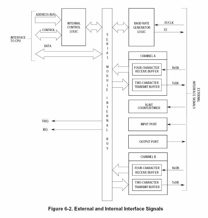
Implementation of the UART device: (drawing from Phil Anderson’s notes)
The figure that follows shows the internal organization of the serial interface device.
Several registers are exposed to the CPU bus including the transmitter buffer, the receiver buffer, the status register and various configuration registers.
Those registers that may place data on the data bus are connected to it via tri-state buffers. Registers that can only be written into are just connected on the data bus as they never drive it (only read from it). The core processing happens at the shift registers. Data to be transmitted are first copied into a shift register and then they are “shifted out” onto the external connection. Similarly, data received from the external connection are placed into a shift register until all 8 bits are received. In the most commonly used configuration, three external wires are used for communication. One is connected to the ground for reference as we use voltages for representing logical values. The other two are used respectively for transmitting and for receiving. For two UARTS to communicate we connect the ground wires and then interchange the transmit and receive wires. This is called a CROSS configuration as if drawn on paper the transmit and receive wires cross each other. There are several standards for serial communication. One that is commonly used (e.g., the serial port of your PC) is the RS232. It defines both the logical format of characters (which is what we described) and the voltages used for communicating values. In the original RS232 specification -12 is used for 0 and +12 for 1. 0v is used for idle. There have been several variations that use different voltages (e.g., 5v or 3.3v). A commonly used discrete device for generating RS232 compatible signals is MAX232 (search the net for the datasheet).
In more detail the
serial device on the ultragismo processor is organized as follows (please refer
to the user’s manual section 6 for additional information if you are interested
– the exact design is beyond the scope of this lecture/course):