Lecture 17
Andreas Moshovos
Introduction to
Interrupts/Exceptions: Using Interrupts with the UART
In the previous lecture we have seen a way to interface (programmatically) with the serial device. For this purpose we used “polling”, that is busy-waiting. Any time we wanted to communicate with the serial device we had to first probe the status register to see if it is available (if we wanted to send a character) or whether a character has been received. We had to keep probing the status register until the desired condition was met. This is completely counter productive as we consumed all our processing power just waiting. Moreover, while we have not seen a concrete example of this, it turns out that if we have to communicate with multiple devices, writing code that uses polling for all devices simultaneously is at the very least complicated and in some cases it will be virtually impossible. We use this discussion as a motivation for another way for communicating with devices called interrupts. We will later see that interrupts are a very powerful mechanism that can be used to support multitasking, handling of exceptional conditions (i.e., unexpected results during calculation such as a division with zero or overflow), emulation of unimplemented (in hardware) instructions, single-step execution for debugging, and operating system calls/protection among others. So, while for the time we will focus on a very specific application of interrupts please keep in mind that this is just a stepping stone towards explaining the diverse applications of interrupts.
(a note on terminology: the terms interrupt and exception are commonly used to refer to the same concept, often interrupts is used for external device induced requests whereas exception is used for interrupts that are caused by instruction execution. There is no common usage of these terms. Here, we will use the two terms interchangeably to refer to the same concept and we will not make an attempt to differentiate between external of program induced interrupts)
As we have seen, polling is almost the equivalent of a real-life scenario where you hand-off to work to someone and then you keep bugging them all the time asking whether they are done. Interrupts on the other hand are quite different. When we hand-off some work to someone else we also ask them to let us know when they are done. This way we do not need to keep asking them all the time whether they are done. When the work is finished they will come back and notify us.
Here’s a high-level view of the interrupt mechanism:
1. Say the processor is executing instructions.
2. At some point in time, a device requests an interrupt.
3. Later on the processor decides to grant that request. This amounts to completing the execution of the current instruction and then inducing a call to a specialized routine that is called an interrupt handler. The call to the interrupt handler is also a special call in that it must save sufficient information so when eventually the interrupt handler finishes, the processor can resume executing instructions immediately after the instruction that finished prior to inducing the call to the interrupt handler.
There are several requirements that must be met for interrupts to work.
1. We need a mechanism for devices to request interrupts.
2. We need a mechanism for inducing calls to the interrupt handler.
3. We need a mechanism to let the device know that its interrupt request was handled.
4. We need a way of determining where is the interrupt handler (that is where in memory its instruction reside).
5. We need a mechanism for saving and restoring all appropriate machine state (registers plus memory) that may be affected across a interrupt handler call.
The solutions to all these requirements entail hardware units, software and several conventions that must be followed for everything to work as expected. In what follows we start explaining the 68k interrupt model. Where appropriate we abstract away some of the details for clarity. The full interrupt handling model can be found in the 68k user’s manual (section 4.5 at the timing of this writing).
Let’s us first look at the requirements.
REQUIREMENTS #1 and #3: ASKING FOR AN INTERRUPT AND GRANTING THE REQUEST
The device asks for an interrupt, the processor grants that request at a convenient time and informs the device. One straightforward mechanism uses two wires at the physical level. One wire is directed from the device to the CPU (we can call it the Interrupt-Request) whereas the second is directed from the CPU to the device (we can call it Interrupt-Granted). When the device wants to request an interrupt it asserts the interrupt-request signal. When the CPU grants the interrupt, it responds by asserting the Interrupt-Granted signal. This process of “asking” and “granting” is often called a hand-shake.
REQUIREMENTS #2 and #4: INDUCING A CALL TO THE INTERRUPT HANDLER – WHERE IS THE INTERRUPT HANDLER?
With these in place, we next consider cover requirement 3, that is how to induce a call to an interrupt handler. How do we know where in memory is the interrupt handler (which is just a piece of software)? One straightforward solution to this would be to use a hardwired (i.e., decided at designed time and built into the CPU design) address. For example, we could have the interrupt handler to be at address $90000 for all interrupt requests. In fact, some CPUs do exactly that. So all external devices share a common interrupt handler. The interrupt handler then in software probes all appropriate devices to figure out which device actually requested the interrupt. Inducing a call to the interrupt handler is straightforward, change the PC to the interrupt handler’s start address ($90000 in our example) after we have saved somewhere (e.g., on the stack) the current value of the PC so that we can return back to it once the interrupt handler has finished.
REQUIREMENT #5: SAVING/RESTORING STATE
As an interrupt appears to be just like a call we can always use the stack to save and restore state as needed. This can be done automatically by the hardware or we can simply rely on software. There may be odd bits of state that has to be stored depending on the implementation. These may require special hardware support. For the time being we have no context to really discuss this issue.
HOW 68K MEETS THE 5 REQUIREMENTS
With this high-level understanding of a straightforward solution for the aforementioned requirements we can now start discussing the way 68k handles these requirements. There are lots of details that we need to cover. The reason there are so many details is the following: When the 68k designers made the final decisions they had a complete view of all requirements that they had to support and in addition they had a very good understanding of the underlying technological tradeoffs. Thus they came up with the best in their view solution for meeting all requirements. Some of the choices that they made may seem unnecessary or complicated at first, however, eventually once most aspects of interrupts are explained you should be able to appreciate/understand them better.
1. How Devices Request Interrupts: Instead of just one interrupt request wire, the 68k provides seven, IRQ1 through IRQ7. These request lines are prioritized in hardware and thus they correspond to seven different interrupt levels. Interrupt level 7 has the highest priority. These seven interrupt request lines allows us to directly connect up to seven external devices (later on we will see that by “chaining” devices together we can connect a lot more).
2. How the CPU informs a device that its interrupt request has been granted: There are seven interrupt acknowledgement lines, IACK1 through IACK7 (active low). The processor asserts the appropriate line upon granting an interrupt request. The exact hand-share is a bit more complicated in order to facilitate a lot of flexibility in determining where is the interrupt handler for each device. We will return to this topic shortly.
3. How the CPU determines where is the interrupt handler: The 68k uses the concept of interrupt vectors. That is, a number (vector index) is assigned to each interrupt request (we will see how) and then this vector is used as an index into a table in memory that contains the addresses for all interrupt handlers available. This is similar to the jump table we used for implementing the switch statement. In 68k there are 256 such interrupt vectors. The interrupt vector table starts at memory address 0 and ends at address 256x4-1 = 1023 = $3ff. So each interrupt request is assigned a vector number from 0 to 255 and then the processor automatically accesses the corresponding table element and then changes the PC to point to that value and hence execution of the interrupt handler commences.
So given an interrupt request the
question becomes which interrupt vector to use?
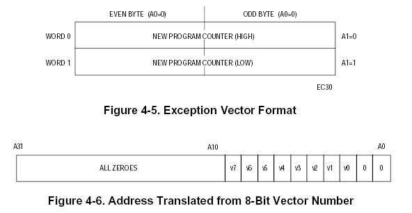
The 68k provides two methods: (1) As part of the hand-shake the device can provide (on the data bus) the interrupt vector it wishes, and (2) the device can request an automatic generation of the vector. The details of the protocol used for this exchange can be found in the 68k user’s manual and are really not that important at this stage. Let’s us focus a bit on the second autovector approach (because the UART “uses” this approach – well in reality it doesn’t, it’s just looks that way, but for the time being let us assume that it does use autovectors). There are 7 autovectors one per interrupt level. These are at the indexes 24+i where i is the interrupt level starting from level 1. So, the interrupt autovector for level 1 is at the index 25 (address 100 = $64) while at index 30 (address $78) is the interrupt vector for level 6. The following two figures show (1) the format of the interrupt vector entries, and (2) the calculation that takes place to determine the address of an interrupt vector (taken from the 68k user’s manual, note that figure 4-6 effectively calculates “interrupt-vector x 4”):
Now we can review the
complete interrupt request/acknowledge/interrupt handler calling/return
sequence:
1. The device requests an interrupt by asserting one of the IRQi lines. Say, this is line IRQ1.
2. The processor completes execution of the current instruction.
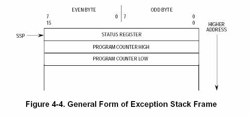
3. The CPU saves on the stack the contents of the contents of the PC (4 bytes) and then of the STATUS register (2 bytes). This is done because the SR contains the CCR which is an implicit target and source of many instructions, hence it is part of machine state that should be preserved (the SR should contain the value it had prior to the interrupt independently on what happens inside the interrupt handler). They could have used software to save the SR but there maybe issues with nested interrupts. Thus the stack looks as follows:
4. The processor asserts the IACK1 line indicating that it is granting the interrupt request.
5. The device responds either with a complete interrupt vector (that is a number between 0 and 255) or requests an auto-vector. For our example let us assume the second, thus the device will request an auto-vector at level 1.
6. The CPU accesses the interrupt vector table using the interrupt vector or the auto-vector number for the device. Since we assumed auto-vectors, the CPU will access memory addresses 100 through 103, will treat these as a long word, then will treat this long word as an address and write it into the PC. Effectively, execution now will resume at that address which is presumed to be holding the first instruction of the interrupt handler.
7. Upon completion the interrupt handler uses the instruction rte which restores both the PC and the status register from the stack (it’s different from rts which only restores the PC).
The Interrupt
Controller:
Before we start writing code for communicating with the UART using interrupts there are few other “details” that we need to discuss about. First, because there are seven external interrupt lines and because the processor may chose to temporarily ignore requests from any level it wishes – except level 7 – there is a specialized unit that acts as a mediator between the processor and external devices. This is the interrupt controller. The interrupt controller can be though as a specialized device with its own registers which can be used by the CPU to enable or disable certain requests or to find out where a request came from.
So in reality the CPU only provides three signals, IPL0, IPL1 and IPL2 for accepting requests for interrupts (instead of IRQ1 through IRQ7). When these signals form the number 0 then there is no request and when they form any other number, the CPU interprets this number as the level of the requested interrupt (1 through 7). It is the interrupt controller that provides the seven external IRQ lines. It then encodes the highest request onto the IPL lines.
Because interrupt requests are truly that the CPU has the option to ignore them if it so wishes. The mechanism for doing so is the current interrupt priority. This is a number between 0 and 7 and can be found in bits 10-8 of the Status Register:
![]()
![]()
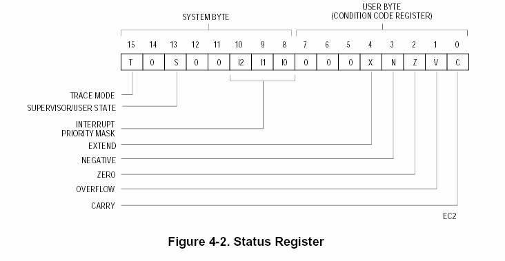
An interrupt request is granted only if the interrupt priority is less than the level of the request. That is, if the priority mask is 0, then all interrupt requests are granted, if the priority mask is 5 only the requests at level 6 and 7 will be granted. The only exception to this rule is level 7 which is always granted no matter what. This is why level 7 is called a non-maskable interrupt. We can change the interrupt priority by writing to the SR register (we can do this only if the CPU is in “supervisor” mode, which means that bit 13 of the SR is 1 – on the ultragismo this is always the case, on a real system this should be the case when the instructions are part of the operating system kernel – more on this later):
move.w #$2200, SR à make SR = 0010 0010 000 0000, the underlined 1 is for staying in the supervisor mode, and the bold three bit value sets the interrupt priority to 2.
Important – The CPU automatically masks off interrupts: Upon granting a request at level i, and after the CPU saves the SR on the stack it automatically sets the priority mask at level i (i.e., writes i into the priority mask field of SR). This is done so that while the interrupt handler at level i is running it will not be interrupted by a request from a lower or same priority device.
The SR register controls
the CPU’s interrupt behavior. There are other memory mapped registers that
control the interrupts controller’s behavior.
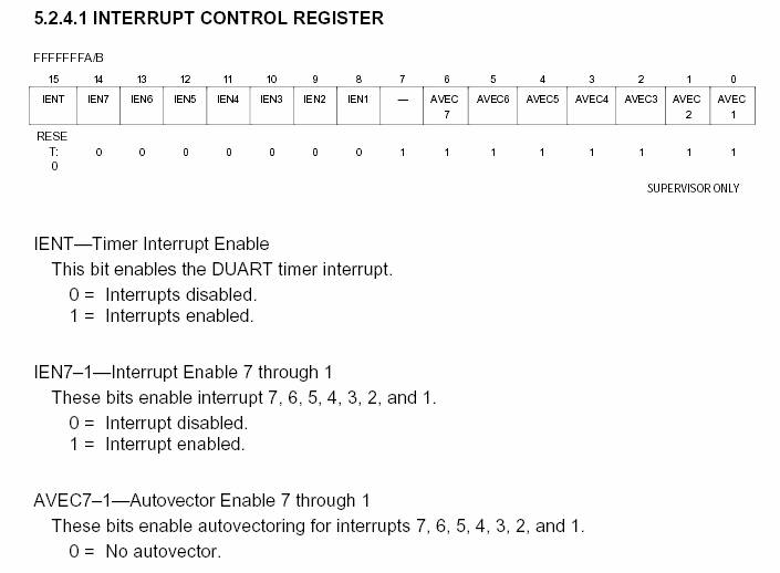
Please refer to section 7.1 of your ultragismo manual for additional details about the interrupt controller. It contains three internal registers that are used to: (1) enable interrupts at each level, (2) enable autovector interrupt request generation per level, and (3) allow the interrupt request/ack lines to be disabled so that they can be used for different purposes (because there are limited pins on the processor some devices share pins with these lines and you can programmatically chose where you want the device or the interrupt). Note that the monitor initializes these registers in such a way so that you can use interrupts with the UART without having to change them. For this reason we will not cover these registers in the lectures. The most relevant is the interrupt control register (ICR). The following figure explains its fields and their use (the register is 16 bits long and resides at address $fffffffa):
USING INTERRUPTS
WITH THE UART:
Let’s us now discuss how we can use interrupts with the UART.
We will write a program that continuously sends a character through the UART using polling. The character is initially the space (32) but through interrupts this character should change to be whatever is received from the UART. The change of the character will happen asynchronously with respect to our polling sending program.
Here’s the core of the character-send program that uses polling:
SRB equ $fffff7f3
TBB equ $fffff7f7
TBB equ $fffff7f7
org $30000
thechar dc.b ‘ ‘ ; this is the character being sent – it is read by our program and will be written by the interrupt handler
org $20000
INITIALIZATION CODE WILL GO IN HERE
flood ;
for ever, keep sending the character through the UART
btst.b #2, SRB
beq flood
move.b thechar, d0
move.b d0, TBB
bra flood
We can now write the interrupt handler (at the end we will write the initialization code which will cause this interrupt handler to be called when the UART receives a character – so for the time being assume that this has been done):
receiver move.l d0, -(a7) ; save d0 since we will change it
btst.b #0, SRB ß I do not think this instruction is needed but I cannot check this (it was part of an example that I was given long time ago)
; ultimately whether is needed or not depends on the UART’s programming model
move.b RBB, d0 ; read character from receiver buffer and write it into memory location “thechar”
move.b d0, thechar
move.l (a7)+, d0 ; restore the d0
rte
Finally, we can write the initialization code. There are several things that we need to do and writing this code requires that we explain a few more registers that exist within the UART device.
Table 8 of your ultargizmo manual provides a full list of all UART registers. Here they are:
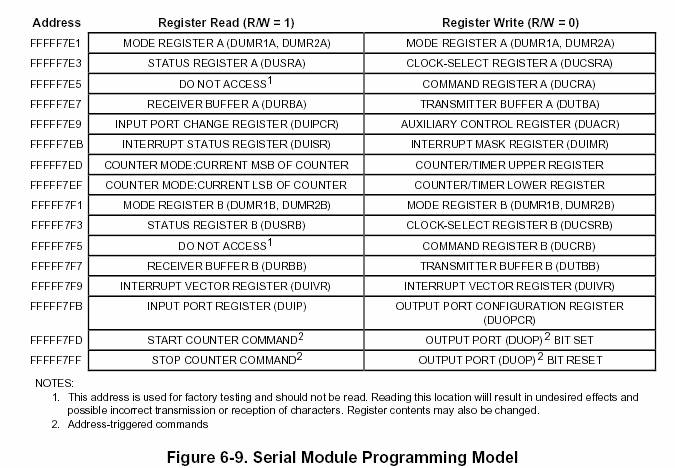
The registers that are relevant for our example are:
1. Interrupt Status Register (DUISR or just ISR). This we read.
2. Interrupt Mask Register (DUIMR or just IMR). This we write for configuring the UART to ask for interrupts.
3. Interrupt Vector Register (DUIVR or just IVR). This we write for configuring the UART to ask for a specific interrupt vector.
IMR is used to program the UART to request interrupts for various events. One of these events is receiving a character. The format of this register is as follows:
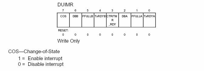
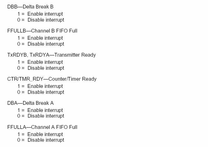
As you can see there are several events that we can program to generate interrupts. We are interested in receiving characters. So, we should enable FFULLB which really means that the RBB contains a character (the term fifo is unfortunate in this case). So, we want to write the value %00100000 into this register.
IVR is used to request the appropriate vector for this device. This is why earlier we said that the UART behaves as if it uses autovectors. It does not. It uses the other mode where it provides the actual vector. However, the ultragismo designers used exactly the same vector that would have been used had they used autovectors. Because the UART is at level 4 (physical connection) we have to request vector 24+4 = 28, hence we must write 28 into the IVR.
The ISR provides the request status for all possible sources of interrupts. Its format follows. We need this register in order to be able to figure out (from within the interrupt handler) the reason for which the interrupt occurred and the interrupt handler was called. Observe that there is one interrupt handler for this device while through the IMR we can program the device to request interrupts for up to 8 different conditions. We will not use this register for our example since we will enable interrupts only for receiving characters. However, if we were to enable multiple interrupt through IMR then we would need to access ISR inside the interrupt handler to determine which of the multiple causes was the reason the handler was invoked.

So, here’s the complete code (initialization in bold):
SRB equ $fffff7f3
TBB equ $fffff7f7
TBB equ $fffff7f7
ISR equ $fffff7eb
IMR equ $fffff7eb
IVR equ $fffff7f9
org $30000
thechar dc.b ‘ ‘ ; this is the character being sent – it is read by our program and will be written by the interrupt handler
org $20000
move.l #receiver,
$70 ; write into the interrupt vector
28 entry the address of our interrupt handler
; it
is important to do this prior to enabling the interrupt
move.b #28, IVR ; tell the UART to ask for interrupt vector 28
move.b #%00100000, IMR ; tell
the UART to ask for interrupts when receiving a character
move.b #$2300, SR ; Retain
supervisor status and set level to 3 so that the CPU will accept requests from
the UART which is at level 4
; the
ICR register must also be set to enable interrupts at level 4 but this is done
by the monitor
flood ;
for ever, keep sending the character through the UART
btst.b #2, SRB
beq flood
move.b thechar, d0
move.b d0, TBB
bra flood
receiver move.l d0, -(a7) ; save d0 since we will change it
btst.b #0, SRB ß I do not think this instruction is needed but I cannot check this (it was part of an example that I was given long time ago)
move.b RBB, d0 ; read character from receiver buffer and write it into memory location “thechar”
move.b d0, thechar
move.l (a7)+, d0 ; restore the d0
rte