Lecture 18
Andreas Moshovos
Spring 2005
Using Interrupts
Continued: Other causes of interrupts and an example of how they can be used to
emulate new or unimplemented (in hardware) instructions.
In the previous lecture we have seen how interrupts can be used to communicate with I/O devices. We noted that the interrupts mechanism has a lot more diverse applications. The vector table definition for the 68k points to some of these applications:
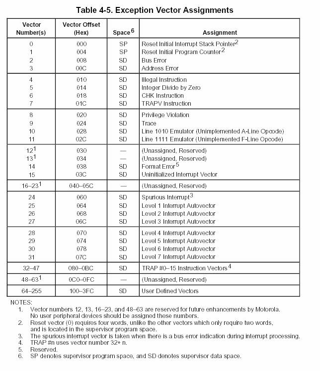
For example, we can see that interrupt vector 5 is used whenever a division with zero is attempted. Similarly, vectors 32 through 47 are used whenever the TRAP instruction is executed (the actual vector used depends on the argument to the TRAP instruction). The TRAP instruction is used to implement system calls (that is operating system calls). Vector 3 is used on an address error, that is whenever an instruction tries to access attempts to access a word or a long word value or an instruction at an odd memory address (misaligned access). The Bus Error exception is used for other purposes (e.g., accessing a portion of memory that is not implemented in a particular design).
Whenever an exception occurs the 68k saves the PC and the SR on the stack, enters supervisor mode and calls the interrupt handler as specified by the appropriate vector.
TRAPs are typically used to implement an operating system. Initially, after reset the system runs in supervisor mode. The operating system which runs at that time runs in the supervisor mode and sets the TRAP vector to point to a known entry point in the OS. Then the first user program is run after the supervisor bit in the SR register is turned off. So, now the user program cannot access everything in the machine. The only way the user program can access devices is through a system call to the OS. TRAPs are used to implement these system calls. The moment the user program executes a TRAP, the OS is invoked using the TRAP vector which it set previously (during the initialization). The moment the TRAP executes, 68k automatically reverts to supervisor mode. This way the machine mode is temporarily again supervisor while running the OS to service the system call. The moment the OS finishes with the system call, it executes an RTE instruction and hence returns immediately after the TRAP. AT this point however, SR is restored from the stack and hence we are back to supervisor mode.
Emulating
non-implemented instructions
As an example of other uses of interrupts we will use vector 10. This interrupt vector is used whenever the CPU attempts to execute an instruction whose opcode is of the form $Axxx (recall, every 68k instruction is at least two bytes long and note that no 68k instruction is of the form $Axxx).
This interrupt can be used to emulate in software instructions that are not really implemented in hardware. Once our interrupt handling routine is written, the emulated instruction can be used as if it was implemented in the CPU.
For example, it used to be the case that one could get 80386 which implemented the integer subset of the x86 instruction set in hardware (80386 is P4’s grand-grand-“father”). The x86 instruction set, however, included instructions for floating point numbers too. To get hardware for those you had to get the 80387 processor which was a co-processor that worked in tandem with 80386. If you didn’t have the 80387 you could always use interrupts to emulate these instructions in software and still run programs that used them (albeit a lot more slowly than they would run if you had 80387). The same was true of 68000. There was a floating-point coprocessor one had to get separately to have floating-point instructions run in hardware.
As an example we will implement the instruction “bitcount.l Dx”. This is not a 68K instruction. We are defining it.
It takes a single argument which is a D register and counts the number of bits that are 1 in Dx. It operates only on long words and the result is written back into Dx.
Before we emulate the instruction let’s decide on an encoding for it. We will use:
%1010 0000 0000 0ddd
where ddd forms a three bit number which indicated the D register this instruction is using.
So, %1010 0000 0000 0101 encodes “bitcount D5” and %1010 0000 0000 0111 encodes “bitcount D7”.
The only important consideration here is that no other valid 68k instruction uses the same encoding.
Here’s the assembly code for the interrupt handler:
org $28
dc.l bitcount ; initialize interrupt vector to point to our interrupt handler
; may need to define one more vector (can’t test it to double check)
; on the simulator I did have to define another vector too but I believe that the simulator is wrong
org $25000
bitcount
movem.l a1/a0/d0-d7,-(a7) * save registers we will be touching and all D
registers
* on the
stack we have starting from the top: D0 – D7, A0, A1
move.l 42(a7),a0 * get PC of excepting instruction
* we have to
add 10 x 4 bytes for the saved regs
* +2 for the
SR (recall this is an exception)
* SEE FIGURE
(+++) BELOW FOR THE STACK
clr.l d1
move.w (a0),d1 * get actual opcode in d1
* so d1
(word) should be in the form %1010 0000 0000 0ddd
and.w #$0007,d1 * get register index in d0
lsl.l #2,d1 * convert d1 into a long word
table index
*
alternatively we could write add.l d1, d1 twice
move.l a7,
a0 * copy stack pointer into a0
adda.l d1,
a0 * get the address of the
i-th element as indicated by d1
* notice
that the D registers are stored one after the other on the
* other on
the stack effectively forming and array
move.l (a0),
d0 * read into d0 the value of
the source operand register
clr.l d1 * count = 0
nonzero
tst.l d0 * if value == 0 then we are
done, tst just sets the condition codes
* to reflect
the value in D0 (if it’s zero, negative, etc.)
beq zero
btst.l #0,
d0 * if bit 0 of value is 0 do
not increase count
beq bitzero
addq.l #1,
d1 * bit 0 of value is 1
increment count
bitzero
lsr.l #1,
d0 * shift value right by 1 bit
bra nonzero * continue this process until
value becomes 0
zero
move.l d1,
(a0) * modify the appropriate Di
saved value on the stack so that it will
·
change when all D registers are restored
movem.l (a7)+,
a1/a0/d0-d7 * restore registers, this
will also now change the D register
* that was
the destination of the bitcount instruction
addq.l #2, 2(a7) *
increment the saved PC by 2 as if the instruction was executed
rte
* here’s a piece of code that uses the new instruction
BITCOP EQU %1010 0000 0000 0000
org $20000
main
move.l #55, d1
dc.w BITCOP + 1 * amounts to %1010 0000 0000 0000 + 1 or bitcount D1
move.l #55, d6
dc.w BITCOP + 6 * amounts to %1010 0000 0000 0000 + 6 or bitcount D6
FIGURE (+++) HOW THE STACK LOOKS LIKE BEFORE THE FIRST MOVEM INSTRUCTION:
|
(WORD) Top of the stack |
Value of SR |
|
(LONG WORD) +$2 |
Return Address |
|
|
|
|
|
|
The return address is the address of the instruction that caused the interrupt. This is because this is an illegal instruction. For a device interrupt the return address would have been the one of the instruction that will execute next once the interrupt handler exits.
FIGURE (+++) HOW THE STACK LOOKS LIKE AFTER THE FIRST MOVEM INSTRUCTION:
|
Top of the stack |
Value of D0 |
|
+$4 |
Value of D1 |
|
+$8 |
D2 |
|
+$C |
D3 |
|
+$10 |
D4 |
|
+$14 |
D5 |
|
+$18 |
D6 |
|
+$1C |
D7 |
|
+$20 |
A0 |
|
+$24 |
A1 |
|
(NOTE THIS IS A WORD) +$28 |
Value of SR |
|
(THIS IS A LONG WORD) +$2A |
Return Address |
|
|
|
|
|
|
Note that the top of the stack is different the two preceding figures. The top of the stack of the first figure is at distance +$28 from the top of the stack of the second figure.
We use dc.w to specify the bitcount instructions since this is not an actual 68k instruction. The assembler does not understand what “bitcount.l” means. So, we have to explicitly do the translation to the binary encoding used by 68k (which we decided also).
When 68k tries to execute any of the dc.w words as instructions it will find that it knows nothing about them since they do not correspond to any valid instruction. It will then raise on its own the illegal opcode interrupt and hence run our interrupt handler. The interrupt handler will then emulate the behavior of bitcount and hence to a programmer it would look as if bitcount is an actual instruction.
Note that I have tested this code on a simulator of 68k.
Optimized
implementation (you are not responsible for this material for any of the
exams):
There is a way of calculating the bit count of a binary value very quickly. Can you analyze the following code and show why it works (differences with previous implementation in bold)?
This is more of a trick than a concept but many things about computers are about experience. The more tricks you know the better you are equipped to meet future challenges.
This code is given for your “benefit” and is not part of the material you are responsible for.
org $25000
bitcount
movem.l a1/a0/d0-d7,-(a7) * save registers we will be touching and all D
registers
* on the
stack we have starting from the top: D0 – D7, A0, A1
move.l 42(a7),a0 * get PC of excepting instruction
* we have to
add 9 x 4 bytes for the saved regs
* +2 for the
SR (recall this is an exception)
clr.l d1
move.w (a0),d1 * get actual opcode in d1
* so d1
(word) should be in the form %1010 0000 0000 0ddd
and.w #$0007,d1 * get register index in d0
lsl.l #2,d1 * convert d1 into a long word
table index
move.l a7,
a0 * copy stack pointer into a0
adda.l d1,
a0 * get the address of the
i-th element as indicated by d1
* notice
that the D registers are stored one after the other on the
* other on
the stack effectively forming and array
move.l (a0),
d0 * read into d0 the value of
the source operand register
* at this stage d0 contains the value whose bit
count we want to calculate
* the code that follows counts the number of 1
bits and stores the result into d0
move.l d0, d1
andi.l #$aaaaaaaa, d1
lsr.l #1, d1
andi.l #$55555555, d0
add.l d1, d0
move.l d0, d1
andi.l #$cccccccc, d1
lsr.l #2, d1
andi.l #$33333333, d0
add.l d1, d0
move.l d0, d1
andi.l #$f0f0f0f0, d1
lsr.l #4, d1
andi.l #$0f0f0f0f, d0
add.l d1, d0
move.l d0, d1
andi.l #$ff00ff00, d1
lsr.l #8, d1
andi.l #$00ff00ff, d0
add.l d1, d0
move.l d0, d1
lsr.l #16, d1
andi.l #$0000ffff, d0
add.l d1, d0
move.l d0, (a0) * modify the appropriate Di saved value on the stack so
that it will
* change
when all D registers are restored
movem.l (a7)+,
a1/a0/d0-d7 * restore registers, this
will also now change the D register
* that was
the destination of the bitcount instruction
addq.l #2, 2(a7)
rte