Computer Organization
Introducing New Instructions
Andreas Moshovos
Spring 2006
Extending/Changing
the Datapath
We have seen how to design a complete datapath and control. Now let’s see how we can change this datapath to support new or different instructions. Because our instruction encoding is dense and does not allow for the introduction of new instructions, let’s see how we can implement a different LOAD instruction. So, what if we wanted to *replace* load with the following:
LOAD r1 (r2)+
We first start with the behavioral model of this instruction. This is the programmer’s model, or in other words the way the programmer expects this instruction to behave. As a designer, this model is our contract. We have to design a processor that adheres to this model. This way the programmer can reason about program behavior.
So the behavioral model of the new LOAD is:
1. R1 = MEM [R2]
2. R2 = [R2] + 1
3. PC = [PC] + 1
In words, we read R2, use this value as an address to read from memory, the value we read from memory we write into r1. Then we increment r2 by 1. Finally, we increment PC by 1.
Starting from this model let’s see what are the actions that need to take place in the datapath.
Going from the behavioral model to a set of actions that need to take
place in the datapath:
A. First we have to read the instruction into the IR
B. For part (1) we need to do the following:
a. Read R2
b. Read from memory using the value read in step (a) as the address
c. Write the value read from memory in (b) into R1
C. For part (2) we need to do the following:
a. Read R2
b. Add 1 to the value read in step (a)
c. Write the value produced in step (c) into register R2
D. For part (3):
a. Read the PC
b. Add 1 to the value read in step (a)
c. Write the value produced in step (c) into the PC.
Now let’s attempt to assign these actions into cycles. Any *valid* assigned into cycles is acceptable. An assigned to cycles is valid if: (i) it maintains the order of actions (i.e., action B.a happens before action B.b), (ii) and as long as the datapath can support the necessary actions.
Let’s focus on part (i) first, that is assign the actions into cycles. The first two cycles are the same for all instruction because in cycle 1 we read the instruction from memory and in cycle 2 the control looks at it and tries to decide what to do next.
CYCLE 1:
IR <-- MEM[PC] * ACTION A: Read instruction from memory
store it in IR
PC <-- PC + 1 * ACTIONS D.a
through D.c: Increment PC
CYCLE 2:
R1 <-- RF[IR7,6] * NOT NEEDED BY LOAD: Read register R1 (as
specified by bits 7 and 6 or the IR)
R2 <-- RF[IR5,4] * ACTION C.a:
Read register R2
Note that here we did not yet have time to look at the instruction. So, we are performing two reads that *may* be useful. For loads these are useful but we take these actions for all instructions.
CYCLE 3:
MDR <-- MEM[R2]
* ACTION B.b: read value from memory
CYCLE 4:
RF[IR7,6] <--
[MDR] * ACTION B.c: write value read from memory
intro the register file
CYCLE 5:
AluOut <-- R2
+ 1 * ACTION C.b:
add 1 to the value read in action C.a
CYCLE 6:
RF[IR5,4] <-- AluOut * ACTION C.c: write the
value produced in action C.b into R2
This is not the shortest in terms of cycles assignment. We can notice that in CYCLE 3 we can also do C.b:
CYCLE 3:
MDR <-- MEM[R2]
* ACTION B.b: read value from memory
AluOut <-- R2
+ 1 * ACTION C.b:
add 1 to the value read in action C.a
CYCLE 4:
RF[IR7,6] <--
[MDR] * ACTION B.c: write value read from memory
intro the register file
CYCLE 5:
RF[IR5,4] <-- AluOut * ACTION C.c: write the
value produced in action C.b into R2
We cannot do B.c and C.c during the same cycle since they both use the register file’s write port (and there is only one of it).
Is the datapath capable of performing all these actions? Yes, except for Action C.c. For this we need to be able to use bits 5,4 or the IR to specify the target register. Our current datapath has regw connected to IR7,6 or to 1:
ORIGINAL DATAPATH
So, we need to introduce:
(1) The capability of using either IR7,6 or IR5,4 for regw. Here’s the modified datapath:
(2) The capability of passing R2 and 1 as the two arguments to the ALU for addition.
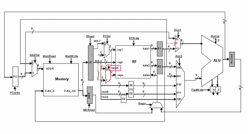
The new control signal rwsel allows us to either use IR7,6 or IR5,4 for regw. The ALU1 signal now becomes a two bit signal as we introduced the option of passing the value of R2 as the first input to the ALU.
Behavioral
Semantics
Let us now closely inspect whether the implementation really adheres to the instruction definition. Our definition says that the new LOAD R1 (R2)+ instruction does:
1. R1 = MEM [R2]
2. R2 = R2 + 1
3. PC = PC + 1
Notice that the way this is written one can reasonably assume that first we do (1) and then we do (2).
What would happen if the instruction was LOAD K1 (K1)+? Our definition then says:
1. K1 = MEM [K1]
2. K1 = K1 + 1
3. PC = PC + 1
At the end, K1 should be the value we read from memory incremented by 1. However, our implementation does do that. What it does is, first load a value from memory using K1 as the address. Then it increments the value K1 had before the memory read by 1 and writes that value into K1.
At this point there are the following two solutions:
1. Rethink the instruction definition. We can rewrite the instruction definition to reflect what we learned while trying to implement it. The definition can become:
a. TMP = R2
b. R1 = MEM [R2]
c. R2 = TMP + 1
d. PC = PC + 1
As we will see in option 2, implementing the first definition requires 6 cycles. Learning from the implementation we can decide that probably our initially choice for the instruction was not really well thought out. Processor designers go through such refinement steps all the time prior to shipping the final design. Sometimes, however, even the best design teams do not necessarily interpret or predict all details. Sometimes, they end up building processors that behave slightly differently than what they planned. In many processor manuals there is often an “Errata” section where the designers explain how the implementation is different than the specification. In other words, most processor manuals can be thought of a two separate sections. The first section is “this is what we planned to build”, and the second “these are the differences in what we build”.