- Red
- Green
- Blue
- Horizontal Sync
- Vertical Sync
The first three signals, red, green and blue, are analog signals that carry the pixel data. The remaining two signals, hsync and vsync, provide the timing information necessary for the monitor to correctly display the pixel data.

|
Figure 1 shows the timing relationship between the video data and the horizontal synch signal. The top waveform, labeled video line, shows typical analog video data for a single scanline. The waveform has a Horizontal Blanking Interval in which no video data is transfered. This period of time is used by a CRT monitor to realign the electron gun in preparation for the next scan line. The Horizontal Blanking Interval is recognized by the monitor through the use of the horizontal sync pulse.
The horizontal sync pulse has three important timing characteristics:
- Front Porch
- Pulse Width
- Back Porch
The front porch of the sync pulse is the delay between the end of the video data of a scanline and initial edge of the sync pulse. The pulse width is simply the period of time that the sync signal is asserted, and the back porch is the delay between when the final edge of the sync pulse and the first piece of data for the next scanline.

|
Figure 2 shows the timing relationship between the video data and the vertical sync signal. The top waveform, labeled video frame, shows typical analog video data for an entire video frame. The waveform has a Blanking Interval in which no video data is transfered. This period of time is used by a CRT monitor to realign the electron gun from the last scanline to the top of the screen again. The Vertical Blanking Interval is recognized by the monitor through the use of the vertical sync pulse.
The vertical sync pulse also has timing specifications for the front porch, the pulse width, and the back porch.
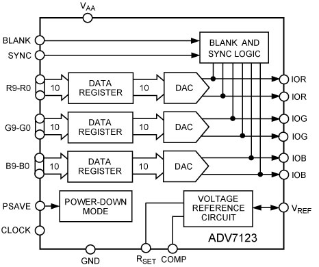
The signals on the left, Blankn, R(9-0), G(9-0), B(9-0), and clock, are controlled by the FPGA. The signals on the right, IOR, IOG, and IOB are connected to a standard VGA connector. Additionally the VSYNC and HSYNC signals of the VGA connector are connected directly to FPGA 0.

|
The propagation delay for the signals between the FPGA and the DAC are shown in the table 1.
| Signals | Min Delay | Max Delay |
| R(9-0), G(9-0), B(9-0) | 1.5ns | 2.0ns |
| Blank | 1.7ns | 2.1ns |
| Clock | 1.7ns | 2.2ns |
The relevant timing signals for the video DAC are shown in table 2.
| Data Setup | 1.5ns (min) |
| Data Hold | 2.5ns (min) |
| Clock to Out Delay | 7.5ns (typ) |
It should be noted that the video DAC adds a clock cycle of delay between the FPGA and the VGA connector on the TM-4, where as the HSYNC and VSYNC signals are connected directly to the FPGA. This means that the pixel data must be driven by the FPGA one cycle earlier then the synchronization data in order for the two to be properly aligned at the VGA connector.